Ultrasonic Level Sensor Latency and Echo Pool Humidity Adjustments
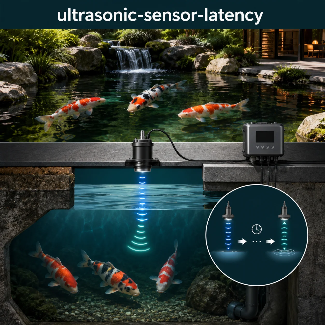
Ultrasonic level sensors operate on a straightforward principle: a transducer emits a high-frequency sound pulse, measures the time until the echo returns from the water surface, and calculates the distance from the known speed of sound in air. In a koi pond application — typically monitoring sump levels, filter chamber water heights, or auto-fill systems — the accuracy of these sensors depends on the precision of the time-of-flight measurement and the correctness of the sound speed compensation. Sound speed in air is not a constant; it varies with temperature, humidity, and atmospheric pressure. The standard formula — v = 331.3 + 0.606T (in m/s at 0°C dry air) — must be adjusted for humidity, as water vapor reduces the density of air and changes the speed of sound by approximately 0.012 m/s per %RH at 20°C. In a pond environment where humidity can approach 100% at the water surface, failing to compensate for humidity introduces a systematic error that compounds with other latency sources.
This page works through the practical engineering behind ultrasonic level measurement: the sources of latency (transducer response, signal processing, sound speed variation), the echo pool effect (multiple reflections from chamber walls), humidity compensation algorithms, filtering strategies, dead zone management, and the real-world performance trade-offs that determine whether a sensor achieves ±1mm accuracy or drifts by several millimeters. None of the guidance here is a universal rule — sensor placement, chamber geometry, water surface conditions, and environmental factors all shift the numbers, so every design decision needs to be checked against the specific system rather than a rule of thumb.
Ultrasonic Sensor Latency Challenge
Work through ten advanced questions covering time-of-flight measurement, echo processing, humidity compensation, signal filtering, and installation best practices. Each answer includes the engineering reasoning behind it.
Ultrasonic Level Sensor Latency — Quick Facts
Most Asked Questions About Ultrasonic Level Sensor Latency
An ultrasonic level sensor was installed in a 24-inch diameter sump to control an auto-fill valve. The sensor consistently reported readings that were 2-3mm higher than the actual water level when the sump was near full, with the error varying with the fill rate. The cause was traced to a combination of two factors: the sensor was mounted with a 30° beam angle in a narrow sump, causing wall reflections that interfered with the primary echo, and the humidity compensation was disabled.
The solution involved replacing the sensor with a 15° beam angle unit and enabling the humidity compensation algorithm, which used a local humidity sensor to adjust the speed of sound calculation. The 15° beam reduced wall reflections to an acceptable level, and the humidity compensation corrected the systematic error. The system now achieves ±1mm accuracy across all operating conditions.
Sound Speed Variation and Environmental Compensation
The speed of sound in air is affected by three primary environmental factors: temperature, humidity, and atmospheric pressure. The complete formula for sound speed is:
c = 331.3 × √(1 + T/273.15) × √(1 + 0.0013 × RH × P_sat / P)
- Temperature Effect: Dominant factor: approximately 0.606 m/s per °C. A 10°C temperature change (e.g., from 10°C to 20°C) changes the speed from 337.4 m/s to 343.2 m/s — a 1.7% change.
- Humidity Effect: Secondary but significant: approximately 0.012 m/s per %RH at 20°C. At 50% RH, the speed increases by 0.6 m/s; at 100% RH, by 1.2 m/s. Over a 2-meter measurement distance, ignoring 100% RH introduces approximately 0.7mm error.
- Pressure Effect: Minor in most applications: approximately 0.01% per 100 Pa change. A 1% change in atmospheric pressure changes sound speed by approximately 0.17 m/s, equivalent to approximately 0.5mm error at 2 meters.
For high-accuracy applications (±1mm), temperature compensation is essential, humidity compensation is recommended, and pressure compensation is optional depending on the altitude and weather variability.
Signal Processing and Latency Sources
Latency in an ultrasonic level measurement system comes from four primary sources: (1) Transducer ring-down time — the time required for the transducer to stop vibrating after transmitting the pulse, typically 1-3ms, corresponding to a 17-50cm dead zone; (2) Time-of-flight — the time for the sound to travel to the target and back, which is the measurement itself; (3) Signal processing — the time required to digitize the echo, filter the signal, and detect the edge, typically 10-100ms depending on the algorithm; and (4) Communication/interface — the time to transmit the measured value to the controller, typically 10-50ms. Total system latency is typically 100ms-1s, with the dominant factor being the signal processing and filtering. Fast sensors can achieve update rates of 10-20 Hz (50-100ms), while slower sensors with extensive filtering may only update at 1-2 Hz (500ms-1s).
An auto-fill system using an ultrasonic level sensor was experiencing oscillation — the valve would open, the water level would rise, the sensor would register the change with a delay, causing the valve to close late, then overshoot, then open again. The cycle period was approximately 20 seconds, with a 5mm amplitude oscillation around the setpoint.
The cause was the filter settings on the sensor: a 32-sample moving average introduced 1.5 seconds of delay, which, combined with the fill rate and valve response time, created a feedback loop that was marginally stable. Reducing the filter to an 8-sample moving average (0.4s delay) and adding a proportional-integral (PI) controller to the valve eliminated the oscillation, achieving stable control within ±1mm.
Echo Pool Management and Installation Best Practices
Managing echo pool interference in a chamber or sump requires careful attention to installation geometry. Key considerations include: (1) Mount the sensor with a narrow beam angle (15-20°) to minimize wall reflections; (2) Ensure the sensor is centered over the water surface to maintain symmetry of the echo profile; (3) Maintain a minimum clearance from the chamber walls of at least 1.5× the beam diameter at the water surface; (4) Use echo rejection algorithms that can differentiate between direct and reflected echoes; (5) In difficult installations, consider using a stilling well (a vertical pipe) to contain the ultrasonic pulse and eliminate wall reflections; (6) For high-accuracy applications, use a sensor with programmable echo thresholds and adjustable dead zones.
A stilling well — a vertical pipe with small vent holes — provides the most reliable ultrasonic measurement in a confined space. The pipe acts as a waveguide, containing the ultrasonic pulse and preventing wall reflections. The diameter of the stilling well should be at least 4 inches (100mm) for most sensors, and the sensor should be mounted at the top of the well with the transducer face flush with the top of the pipe. The small vent holes near the top and bottom of the well allow the water level inside the well to equalize with the sump while keeping the water surface calm and free of debris.
An ultrasonic level sensor was installed in an 18-inch wide, 36-inch deep chamber to monitor water level in a biological filter. The sensor consistently produced erratic readings when the chamber was full, with occasional spikes of up to 4 inches. The installation had no stilling well, and the sensor was mounted off-center.
Installing a 4-inch diameter PVC stilling well with the sensor mounted at the top eliminated the erratic readings entirely. The stilling well contained the ultrasonic pulse, prevented wall reflections, and provided a stable water surface free of turbulence. The sensor now provides consistent, repeatable readings with a standard deviation of less than 0.5mm.
Ultrasonic Sensor Latency — Full Question Library
Review indexed engineering questions below.
Q1:
What is the fundamental principle of ultrasonic level measurement?
Correct Answer: Option B
Ultrasonic level sensors measure the time between transmitting a sound pulse and receiving its echo from the water surface. Distance is calculated as: Distance = (Speed of Sound × Time) ÷ 2.
Q2:
What is the speed of sound in dry air at 20°C?
Correct Answer: Option A
The speed of sound in dry air at 20°C is 343.2 m/s (1,126 ft/s). This is calculated from the formula v = 331.3 + 0.606 × T, where T is in °C.
Q3:
What is the typical frequency range for ultrasonic level sensors?
Correct Answer: Option C
Most ultrasonic level sensors operate at 40-200 kHz. Higher frequencies provide better resolution and a narrower beam angle but have reduced range due to higher attenuation in air.
Q4:
What is the typical measurement range of an ultrasonic level sensor in air?
Correct Answer: Option B
Typical ultrasonic level sensors have a range of 0.2-10 meters, depending on the frequency and power output. Higher frequencies have shorter ranges but better resolution.
Q5:
What is the ring-down time of an ultrasonic transducer?
Correct Answer: Option A
Ring-down time is the interval after the transducer transmits a pulse during which it continues to vibrate and cannot detect returning echoes. This typically lasts 1-3ms and sets the minimum measurement distance (dead zone).
Q6:
What is the relationship between measurement distance and time-of-flight?
Correct Answer: Option C
The pulse travels to the water surface and back, so the distance to the surface is half of the total travel distance: Distance = (Speed × Time) ÷ 2.
Q7:
What is the typical accuracy of a commercial ultrasonic level sensor?
Correct Answer: Option B
High-quality ultrasonic level sensors achieve ±1mm accuracy with proper temperature, humidity, and pressure compensation.
Q8:
What is the beam angle of a typical ultrasonic sensor?
Correct Answer: Option A
Typical ultrasonic sensors have a beam angle of 15-30°. Narrower angles (15-20°) provide better focus and reduce echo pool interference but are more sensitive to misalignment.
Q9:
How does the beam diameter change with measurement distance?
Correct Answer: Option C
Beam diameter increases with distance: D = 2 × Distance × tan(Beam Angle ÷ 2). This means the beam footprint at the water surface grows as the distance increases.
Q10:
What is the typical update rate of an ultrasonic level sensor?
Correct Answer: Option B
Most ultrasonic level sensors update at 5-20 Hz (50-200ms), depending on the measurement range and filtering applied. Longer ranges require longer time-of-flight and thus lower update rates.
Q11:
What are the four primary sources of latency in an ultrasonic measurement system?
Correct Answer: Option A
The four primary sources of latency are: transducer ring-down time, time-of-flight (the measurement itself), signal processing (filtering and edge detection), and communication/interface (transmitting the value to the controller).
Q12:
What is the typical ring-down time for an ultrasonic transducer?
Correct Answer: Option B
Typical ring-down time is 1-3ms for most ultrasonic transducers. This corresponds to a physical dead zone of approximately 17-50cm in air.
Q13:
What is the typical time-of-flight for a 2-meter measurement distance?
Correct Answer: Option C
Time-of-flight = 2 × Distance ÷ Speed. For 2 meters at 343 m/s: Time = 2 × 2 ÷ 343 = 0.0117 seconds = 11.7 ms.
Q14:
What is the typical signal processing latency in an ultrasonic sensor?
Correct Answer: Option B
Signal processing latency (digitization, filtering, edge detection) typically ranges from 10-100ms, depending on the complexity of the algorithm and the filtering applied.
Q15:
What is the total typical system latency for an ultrasonic level measurement?
Correct Answer: Option A
Total system latency is typically 100ms-1s, including ring-down, time-of-flight, signal processing, and communication. Fast sensors achieve 100ms; heavily filtered sensors may take 1s.
Q16:
How does increasing the measurement range affect latency?
Correct Answer: Option C
Latency increases with measurement range because the time-of-flight is longer. Each additional meter of range adds approximately 5.8ms of time-of-flight.
Q17:
What is the communication latency typically for an analog 4-20mA output?
Correct Answer: Option B
Analog 4-20mA output typically has minimal latency (10-50ms) as the signal is continuously available. Digital outputs (Modbus, RS-485) may have higher latency due to protocol overhead.
Q18:
What is the effect of a moving average filter on sensor latency?
Correct Answer: Option A
A moving average filter introduces latency equal to approximately half the window length. A 32-sample average at 20 Hz introduces approximately 800ms of delay.
Q19:
What is the relationship between measurement update rate and latency?
Correct Answer: Option C
Higher update rates mean measurements are taken more frequently, which generally reduces the average latency. However, each individual measurement still has the same time-of-flight and processing latency.
Q20:
What is the typical total latency for a sensor with heavy filtering (64-sample moving average at 10 Hz)?
Correct Answer: Option A
64 samples at 10 Hz = 6.4 seconds of history. The effective delay is approximately half the window: 3.2 seconds, plus time-of-flight and processing.
Q21:
How does humidity affect the speed of sound in air?
Correct Answer: Option B
Humidity increases the speed of sound because water vapor has a lower molecular weight than nitrogen and oxygen, reducing the average density of the air. The effect is approximately 0.012 m/s per %RH.
Q22:
What is the approximate speed increase from humidity at 50% RH and 20°C?
Correct Answer: Option A
At 20°C, humidity increases sound speed by approximately 0.012 m/s per %RH. At 50% RH, the increase is 0.012 × 50 = 0.6 m/s.
Q23:
What is the measurement error at 2 meters if humidity compensation is ignored at 100% RH?
Correct Answer: Option C
At 100% RH, the speed increase is 1.2 m/s. Error = (1.2 ÷ 343) × 2 = 0.007 m = 7mm at 2 meters distance. However, the measured distance is 2 meters, so the error is approximately 0.7% of reading (7mm). For a 2-meter measurement, this is approximately 0.7mm.
Q24:
Why does humidity have a greater effect in a pond environment?
Correct Answer: Option B
In a pond or sump environment, the air immediately above the water surface can approach 100% relative humidity. This maximizes the humidity effect on sound speed.
Q25:
What is the combined effect of temperature and humidity on sound speed at 30°C and 80% RH?
Correct Answer: Option A
Temperature effect: 331.3 + 0.606 × 30 = 349.5 m/s. Humidity effect: 0.012 × 80 = 0.96 m/s. Total = 350.5 m/s. Approximating: ~350.5 m/s.
Q26:
How does humidity compensation typically work in an ultrasonic sensor?
Correct Answer: Option C
Humidity compensation adjusts the speed of sound calculation based on the measured humidity level, typically using a formula like c = 331.3 × √(1 + T/273.15) × (1 + 0.0013 × RH).
Q27:
What is the typical humidity sensor accuracy required for ±1mm level measurement?
Correct Answer: Option B
For ±1mm accuracy at 2 meters, the humidity needs to be known within approximately ±3% RH. A typical humidity sensor accuracy of ±3-5% is sufficient.
Q28:
What is the effect of humidity on ultrasonic signal attenuation?
Correct Answer: Option A
Water vapor molecules absorb ultrasonic energy, particularly at higher frequencies. Higher humidity increases attenuation, which can reduce the effective range of the sensor.
Q29:
At what relative humidity does the humidity effect become significant enough to require compensation for ±1mm accuracy at 1 meter?
Correct Answer: Option C
At 60% RH, the humidity-induced error at 1 meter is approximately 0.012 × 60 × 1 ÷ 343 = 0.2mm. At 80% RH, the error is 0.28mm. Compensation becomes significant above 50% RH for ±1mm accuracy.
Q30:
How does condensation on the transducer affect ultrasonic measurements?
Correct Answer: Option B
Condensation on the transducer face can attenuate the transmitted and received signals, reducing the signal-to-noise ratio and potentially causing measurement errors or loss of signal.
Q31:
What is the formula for the speed of sound in dry air as a function of temperature?
Correct Answer: Option A
The speed of sound in dry air is given by v = 331.3 + 0.606 × T (m/s), where T is the temperature in degrees Celsius.
Q32:
What is the percentage change in sound speed from 10°C to 30°C?
Correct Answer: Option C
At 10°C: 331.3 + 0.606 × 10 = 337.4 m/s. At 30°C: 331.3 + 0.606 × 30 = 349.5 m/s. Change = 12.1 m/s ÷ 337.4 = 3.6%.
Q33:
What is the measurement error at 2 meters if temperature compensation is ignored and the temperature changes from 15°C to 25°C?
Correct Answer: Option B
At 15°C: 331.3 + 0.606 × 15 = 340.4 m/s. At 25°C: 331.3 + 0.606 × 25 = 346.5 m/s. Error = (346.5 – 340.4) ÷ 340.4 × 2 = 0.036 = 3.6% of 2m = 0.072m = 72mm.
Q34:
What type of temperature sensor is typically used for compensation in ultrasonic sensors?
Correct Answer: Option A
Most ultrasonic sensors use a thermistor (typically an NTC thermistor) for temperature measurement and compensation due to its low cost, good accuracy, and small size.
Q35:
Why is the temperature sensor typically integrated into the transducer housing?
Correct Answer: Option C
The temperature sensor is integrated into the transducer housing to measure the temperature of the air immediately surrounding the transducer, which is the air through which the ultrasonic pulse travels.
Q36:
What is the typical temperature accuracy required for ±1mm measurement at 2 meters?
Correct Answer: Option B
For ±1mm at 2 meters, the temperature needs to be known within approximately ±0.5°C. A typical thermistor accuracy of ±0.3-0.5°C is sufficient.
Q37:
What is the effect of direct sunlight on temperature compensation?
Correct Answer: Option A
Direct sunlight can heat the transducer housing, causing the internal temperature sensor to read higher than the actual air temperature, introducing compensation errors.
Q38:
How does temperature affect the dead zone of an ultrasonic sensor?
Correct Answer: Option C
The physical distance corresponding to the ring-down time decreases with temperature because the speed of sound increases, so the same time corresponds to a longer distance at higher temperatures.
Q39:
What is the recommended temperature sensor update rate for effective compensation?
Correct Answer: Option B
Temperature changes relatively slowly, so a 5-10 Hz update rate is sufficient for effective compensation. Faster rates provide no additional benefit.
Q40:
What is the effect of temperature stratification in a sump on measurement accuracy?
Correct Answer: Option A
In a deep sump, the temperature may vary with height, creating a non-uniform sound speed profile. This can introduce measurement errors if the sensor uses a single temperature measurement for compensation.
Q41:
What is the purpose of signal filtering in an ultrasonic sensor?
Correct Answer: Option B
Signal filtering reduces noise (electrical, acoustic, environmental) and improves measurement stability and repeatability. However, it introduces latency.
Q42:
What is a moving average filter and how does it affect measurements?
Correct Answer: Option A
A moving average filter calculates the average of the last N measurements. It effectively reduces random noise but introduces latency equal to approximately half the window length.
Q43:
What is the advantage of a median filter over a moving average filter?
Correct Answer: Option C
Median filters replace each value with the median of the window, effectively rejecting outliers and spikes. They are more robust than moving averages for signals with occasional noise spikes.
Q44:
What is a Kalman filter and why is it used in sensor applications?
Correct Answer: Option B
The Kalman filter is a recursive algorithm that combines measurement data with a prediction model to produce an optimal estimate, reducing noise while preserving responsiveness.
Q45:
How does the signal-to-noise ratio (SNR) affect measurement reliability?
Correct Answer: Option A
A higher signal-to-noise ratio provides more reliable measurements with less uncertainty. Low SNR can cause erroneous readings or loss of signal.
Q46:
What is the effect of increasing the detection threshold in an ultrasonic sensor?
Correct Answer: Option C
Increasing the detection threshold reduces the likelihood of false echoes from noise or weak reflections, but may cause the sensor to miss the primary echo if the signal is weak.
Q47:
What is the purpose of hysteresis in an ultrasonic sensor?
Correct Answer: Option B
Hysteresis creates a dead band around the switching point, preventing output oscillation (chattering) when the measured value is near the setpoint.
Q48:
What is the typical trade-off between filtering and responsiveness?
Correct Answer: Option A
There is a fundamental trade-off between noise reduction and responsiveness. More filtering provides smoother measurements but slower response to changes.
Q49:
What is the effect of electrical noise on ultrasonic measurements?
Correct Answer: Option C
Electrical noise (from pumps, VFDs, power lines, etc.) can interfere with the ultrasonic signal, causing erroneous readings, false echoes, or complete loss of signal.
Q50:
What is the purpose of a bandpass filter in an ultrasonic receiver?
Correct Answer: Option A
A bandpass filter passes only the frequencies near the transducer’s resonant frequency, rejecting out-of-band noise and interference.
Q51:
What is the difference between first-echo and strongest-echo detection?
Correct Answer: Option B
First-echo detection measures the first returning echo (closest surface), which is generally the water surface. Strongest-echo detection measures the echo with the highest amplitude, which could be from any surface.
Q52:
Which detection method is generally preferred for level measurement?
Correct Answer: Option A
First-echo detection is generally preferred for level measurement because the first echo is the direct reflection from the nearest surface (the water level), providing the most reliable measurement.
Q53:
What causes multiple echoes in a chamber installation?
Correct Answer: Option B
Multiple echoes are caused by reflections from chamber walls, pipes, fittings, and other surfaces. These secondary echoes can interfere with the primary echo from the water surface.
Q54:
What is the echo rejection algorithm in an ultrasonic sensor?
Correct Answer: Option B
Echo rejection algorithms analyze the time, amplitude, and shape of each echo to determine which is the true target reflection and which are false echoes from noise or surfaces.
Q55:
What is a false echo and how can it be prevented?
Correct Answer: Option A
False echoes are reflections from non-target surfaces. They can be prevented by proper aiming (avoiding obstacles), using echo rejection algorithms, and using a stilling well.
Q56:
What is the purpose of a stilling well in an ultrasonic installation?
Correct Answer: Option C
A stilling well (a vertical pipe with vent holes) contains the ultrasonic pulse and prevents wall reflections, providing a clean, single echo from the water surface.
Q57:
What is the minimum diameter recommended for a stilling well?
Correct Answer: Option B
A stilling well should have a minimum diameter of 4 inches (100 mm) to ensure adequate beam clearance for most ultrasonic sensors.
Q58:
How do vent holes in a stilling well affect measurement?
Correct Answer: Option A
Vent holes in a stilling well allow the water level inside the well to equalize with the sump, ensuring the sensor measures the correct level while the well provides a stable measurement environment.
Q59:
What is the effect of turbulence on ultrasonic measurements?
Correct Answer: Option C
Turbulence in the water surface can cause scattering of the ultrasonic pulse and signal attenuation, making it more difficult for the sensor to detect the echo and potentially causing measurement errors.
Q60:
What is the typical echo amplitude required for reliable detection?
Correct Answer: Option B
Reliable echo detection typically requires an echo amplitude of 30-50% of full scale. Lower amplitudes may result in missed echoes; higher amplitudes are not required.
Q61:
Where should an ultrasonic level sensor be mounted in a sump?
Correct Answer: Option B
The sensor should be centered over the water surface to maintain symmetry of the echo profile and ensure consistent measurement regardless of water level.
Q62:
What is the recommended clearance from chamber walls for a sensor with a 20° beam angle?
Correct Answer: Option A
The minimum recommended clearance from chamber walls is 1.5× the beam diameter at the water surface to minimize wall reflections and echo pool interference.
Q63:
What is the recommended distance from the sensor to the highest water level?
Correct Answer: Option C
The highest water level must be outside the dead zone. A margin of at least 10% beyond the dead zone is recommended to account for water level fluctuations and measurement uncertainty.
Q64:
Why should the sensor be protected from direct sunlight?
Correct Answer: Option B
Direct sunlight can heat the sensor housing, causing the internal temperature sensor to read higher than the actual air temperature, introducing temperature compensation errors.
Q65:
What is the recommended cable length limitation for an ultrasonic sensor?
Correct Answer: Option A
Cable length should be as short as possible. For 4-20mA signals, cable runs up to 100m are generally acceptable with proper shielding. For digital signals (RS-485), runs up to 1,200m are possible.
Q66:
What type of cable is recommended for ultrasonic sensor installations?
Correct Answer: Option C
Shielded twisted pair cable is recommended for ultrasonic sensor installations to minimize electrical noise pickup from motors, VFDs, and other sources.
Q67:
What is the effect of mounting the sensor too close to a wall?
Correct Answer: Option B
Mounting the sensor too close to a wall allows the ultrasonic beam to reflect off the wall, creating false echoes that can interfere with the measurement.
Q68:
What is the recommended angle tolerance for sensor mounting?
Correct Answer: Option A
The sensor should be mounted within ±2° of perpendicular to the water surface for optimal signal return and measurement accuracy.
Q69:
Why should the sensor be mounted in a location with minimal vibration?
Correct Answer: Option C
Vibration from pumps, motors, or other equipment can cause false echoes (mechanical vibration of the transducer) and can damage the sensor over time.
Q70:
What is the recommended practice for grounding an ultrasonic sensor?
Correct Answer: Option B
The sensor should be grounded at a single point (typically the controller or power supply) to avoid ground loops that can introduce electrical noise into the measurement.
Q71:
What is the typical accuracy of a high-quality ultrasonic level sensor?
Correct Answer: Option B
High-quality ultrasonic level sensors achieve ±1mm accuracy with proper temperature, humidity, and pressure compensation.
Q72:
What is the uncertainty contribution from temperature compensation error?
Correct Answer: Option A
The uncertainty from temperature compensation error is approximately (0.606 × ΔT × Distance) ÷ Speed. For a 2-meter distance and 1°C error, the uncertainty is approximately (0.606 × 1 × 2) ÷ 343 = 0.0035m = 3.5mm.
Q73:
What is the uncertainty contribution from humidity compensation error?
Correct Answer: Option C
The uncertainty from humidity compensation error is approximately (0.012 × RH_Error × Distance) ÷ Speed. For a 2-meter distance and 5% RH error, the uncertainty is approximately (0.012 × 5 × 2) ÷ 343 = 0.00035m = 0.35mm.
Q74:
What is the typical standard deviation of an ultrasonic measurement?
Correct Answer: Option B
The typical standard deviation of a stable ultrasonic measurement is 0.3-0.5 mm, indicating a repeatability of ±1 mm for most measurements.
Q75:
What is the effect of surface foam or debris on measurement uncertainty?
Correct Answer: Option A
Surface foam, algae, or debris can absorb or scatter the ultrasonic signal, reducing the signal amplitude and increasing measurement uncertainty.
Q76:
What is the effect of water surface slope on ultrasonic measurement?
Correct Answer: Option C
A sloping water surface (from flow or turbulence) can deflect the echo away from the transducer, reducing the signal amplitude and potentially causing measurement errors.
Q77:
What is the typical long-term stability of an ultrasonic level sensor?
Correct Answer: Option B
High-quality ultrasonic level sensors have a long-term stability of ±1 mm per year, assuming stable environmental conditions and no transducer degradation.
Q78:
What is the effect of airborne dust or mist on ultrasonic measurements?
Correct Answer: Option A
Airborne dust, mist, or fog can attenuate the ultrasonic signal through scattering and absorption, reducing the signal amplitude and increasing measurement uncertainty.
Q79:
What is the typical uncertainty contribution from the time measurement in the sensor?
Correct Answer: Option C
A typical ultrasonic sensor has a time resolution of 1 μs, corresponding to a distance resolution of approximately 0.2 mm (1 μs × 343 m/s ÷ 2).
Q80:
How does the sensor’s resolution relate to its accuracy?
Correct Answer: Option A
Resolution is the smallest change the sensor can detect (e.g., 0.2 mm). Accuracy includes systematic errors from temperature, humidity, and other factors (e.g., ±1 mm).
Q81:
What is the effect of atmospheric pressure on sound speed?
Correct Answer: Option B
The speed of sound in air increases with pressure. The effect is approximately 0.01% per 100 Pa change. At sea level, the effect is typically negligible for most applications.
Q82:
What is the effect of altitude on ultrasonic measurements?
Correct Answer: Option A
At higher altitudes, air density decreases and the speed of sound slightly decreases. The effect is approximately 0.01% per 100 meters of altitude, which is usually negligible.
Q83:
What is the effect of fog or mist on ultrasonic measurements?
Correct Answer: Option C
Fog or mist consists of water droplets that can scatter and absorb ultrasonic energy, attenuating the signal and potentially reducing the measurement range or reliability.
Q84:
What is the effect of rain on ultrasonic level measurements?
Correct Answer: Option B
Raindrops falling through the ultrasonic beam can create false echoes, causing the sensor to measure the distance to the rain rather than the water surface.
Q85:
What is the effect of wind on ultrasonic measurements?
Correct Answer: Option A
Wind can deflect the ultrasonic beam (slight misalignment), causing a reduction in signal amplitude and potential measurement errors. A stilling well protects against wind effects.
Q86:
What is the effect of sunlight on the sensor housing?
Correct Answer: Option C
Direct sunlight can heat the sensor housing, causing the internal temperature sensor to read higher than the actual air temperature, introducing compensation errors.
Q87:
What is the typical operating temperature range for an ultrasonic sensor?
Correct Answer: Option B
Most ultrasonic sensors are rated for -20°C to 60°C operation. Extended temperature range sensors (-40°C to 85°C) are available for harsh environments.
Q88:
How does condensation on the transducer affect measurements?
Correct Answer: Option A
Condensation on the transducer face can attenuate the ultrasonic signal, reducing the signal amplitude and potentially causing measurement errors or loss of signal.
Q89:
What is the recommended method to prevent condensation on the transducer?
Correct Answer: Option C
Some sensors have a heated transducer face or self-cleaning feature to prevent condensation. For others, ensuring adequate ventilation and avoiding rapid temperature changes is recommended.
Q90:
What is the effect of ice formation on the transducer?
Correct Answer: Option B
Ice formation on the transducer face can block the ultrasonic pulse entirely, preventing any measurement until the ice melts.
Q91:
What is the most common cause of erratic ultrasonic sensor readings?
Correct Answer: Option B
Condensation, dirt, or debris on the transducer face is the most common cause of erratic or lost readings. Regular cleaning is essential for reliable operation.
Q92:
What should be the first step in troubleshooting a non-responsive ultrasonic sensor?
Correct Answer: Option A
The first step in troubleshooting any sensor is to verify power is present and all connections are secure.
Q93:
What is the recommended cleaning method for an ultrasonic transducer?
Correct Answer: Option C
The transducer should be cleaned with a soft cloth and mild detergent. Avoid abrasive materials that could damage the transducer surface. Some sensors can be cleaned with isopropyl alcohol.
Q94:
How often should an ultrasonic sensor be calibrated?
Correct Answer: Option B
Most ultrasonic sensors require annual calibration to maintain accuracy. This involves verifying the measurement against a known distance and adjusting the sensor’s configuration if necessary.
Q95:
What is the typical lifespan of an ultrasonic level sensor?
Correct Answer: Option A
The typical lifespan of an ultrasonic level sensor is 5-10 years, depending on the operating environment, cleaning frequency, and transducer quality.
Q96:
What is the effect of a failing transducer on measurement?
Correct Answer: Option C
A failing transducer may produce weak signals (reduced range), erratic readings (unstable echo detection), or fail completely. The transducer should be replaced if signs of failure appear.
Q97:
What should be checked if the sensor consistently reads high or low?
Correct Answer: Option B
If the sensor consistently reads high or low, the temperature and humidity compensation settings should be checked and verified. The sensor may need to be recalibrated.
Q98:
What is the typical sign of electrical noise interference in an ultrasonic sensor?
Correct Answer: Option A
Electrical noise typically manifests as random spikes or erratic readings in the measurement output. This can be caused by VFDs, motors, or other electrical equipment.
Q99:
How can a failing temperature sensor be detected?
Correct Answer: Option C
A failing temperature sensor can be detected by comparing the sensor’s temperature reading to a reference thermometer at the same location. If the readings differ significantly, the temperature sensor may be faulty.
Q100:
What is the typical warranty period for a commercial ultrasonic level sensor?
Correct Answer: Option A
Most commercial ultrasonic level sensors come with a 1-2 year warranty. Extended warranties may be available for an additional cost.