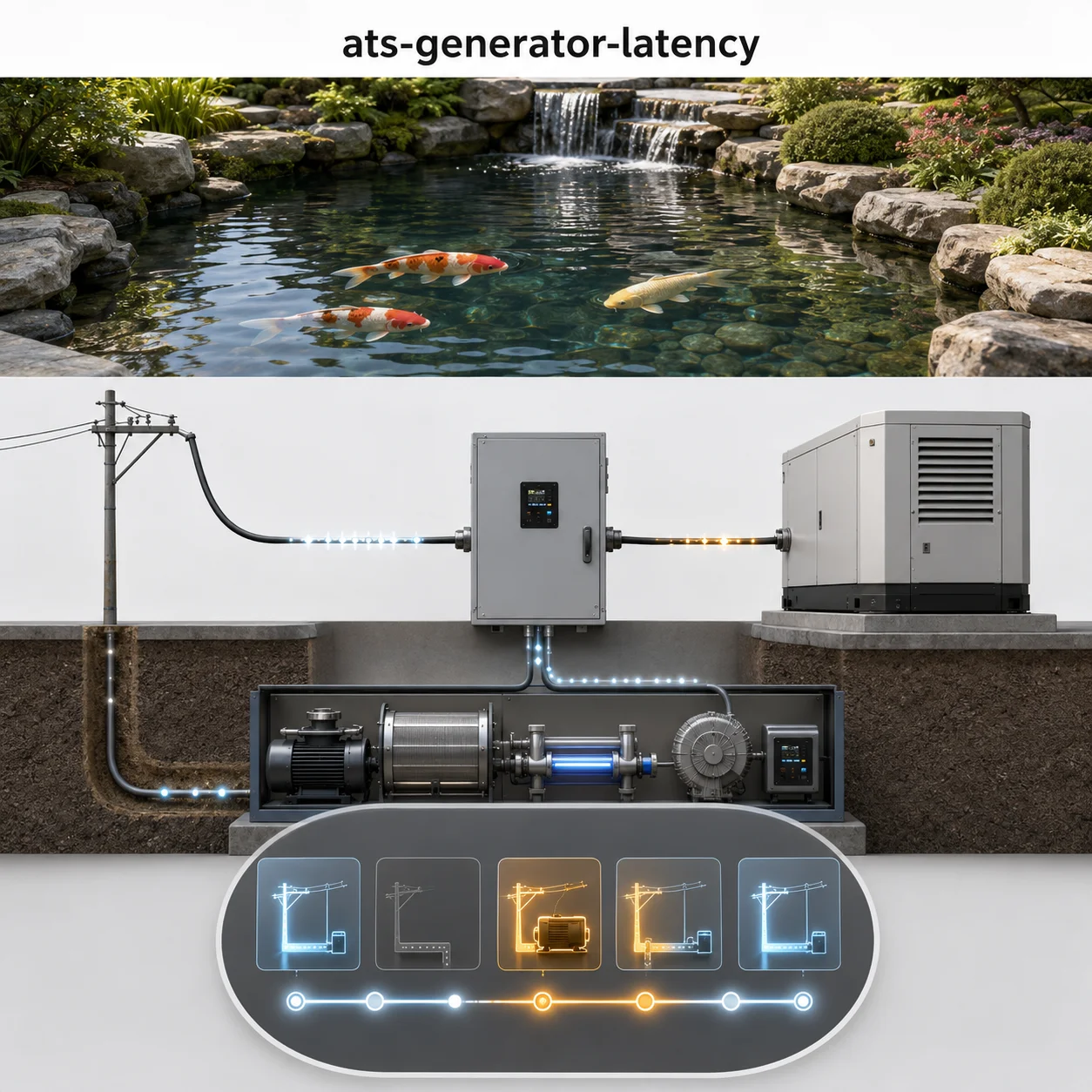
Backup Generator Automatic Transfer Switch (ATS) Latency and Life-Support Failovers
An Automatic Transfer Switch (ATS) is the critical interface between the utility feed, a backup generator, and the life-support systems that depend on uninterrupted power. The ATS monitors utility voltage and frequency; upon detecting a sustained outage, it initiates a transfer sequence that includes generator starting, voltage and frequency validation, and mechanical transfer of the load from the utility source to the generator. The total latency — from utility failure to load restoration — is the sum of generator cranking time, ATS sensing and decision delay, transfer mechanism travel time, and breaker operation. In life-support applications, every millisecond counts, and the difference between a 10-second and a 30-second transfer can determine whether critical equipment remains operational.
This page works through the electrical engineering behind ATS latency: the standards that govern transfer time (NFPA 110, UL 1008, IEC 60947), the physics of generator start-up and synchronization, the types of transfer switches and their respective transfer times, the logic controllers that sequence the event, and the failover strategies that ensure continuity of power to life-support circuits. None of the guidance here is a universal rule — generator size, engine type, ATS design, and the specific load characteristics all shift the numbers, so every design decision needs to be checked against the specific system rather than a rule of thumb.
ATS Generator Latency & Life-Support Failovers
Work through ten advanced questions covering ATS types, transfer latency, NFPA 110 compliance, generator starting circuits, and life-support failover strategies. Each answer includes the engineering reasoning behind it.
ATS Generator Latency & Life-Support Failovers — Quick Facts
Most Asked Questions About ATS Latency and Life-Support Failovers
On one facility upgrade, the client specified a high-end closed transition ATS to achieve seamless transfer for their critical life-support systems. The system was installed and tested successfully under normal conditions. However, during the first actual utility outage, the generator failed to achieve synchronization with the utility before the ATS’s “synchronization timeout” expired. The ATS defaulted to an open transition, causing a 4-second interruption that tripped several sensitive medical devices.
The root cause was an undervoltage condition on the utility side that was not severe enough to trip the generator start, but severe enough to prevent the generator’s automatic voltage regulator from matching the utility waveform within the allowed tolerance. Adding a wider synchronization window and increasing the generator governor response time resolved the issue, but the lesson was clear: closed transition systems require careful tuning of the synchronization parameters and adequate generator response capability.
ATS Types and Transfer Mechanisms
The transfer switch is the mechanical heart of the emergency power system. Three primary types are used in commercial and life-support applications:
- Open transition (break-before-make): The most common and economical type. The switch disconnects from the utility source before connecting to the generator, ensuring the two sources are never paralleled. Transfer time is typically 2-6 seconds. Suitable for loads that can tolerate a brief interruption.
- Closed transition (make-before-break): The switch momentarily parallels the utility and generator sources during transfer, allowing a sub-100ms seamless transfer. Requires synchronization of the generator to the utility and is more expensive and complex. Essential for loads that cannot tolerate interruption.
- Delayed transition: A variation of open transition where the switch includes a dwell time (typically 10-60 seconds) between disconnecting from one source and connecting to the other. Used when loads require time to discharge or de-energize before re-energizing.
The transfer mechanism itself can be solenoid-operated (fast, but high inrush current), motor-operated (slower, but lower inrush and smoother operation), or manually operated with electrical interlocks for maintenance and bypass. The choice depends on transfer speed requirements, available control power, and mechanical duty cycle.
Generator Starting and Stabilization Dynamics
The generator start sequence is a critical component of total ATS latency. When the ATS detects a utility outage, it sends a start signal to the generator controller. The controller then engages the starter motor, which cranks the engine until it fires and reaches operating speed. The time from start signal to engine firing depends on engine type, temperature, fuel system, and battery condition. Once the engine is running, the generator’s electronic governor and voltage regulator need time to stabilize frequency and voltage within acceptable limits (typically ±5% of nominal) before the ATS will allow transfer. This stabilization time is often overlooked in system design, but it can add 2-5 seconds to total latency.
During a routine weekly test of a critical facility’s backup generator, the ATS failed to transfer the load after the generator started and stabilized. The issue was traced to a failed voltage sensing relay in the ATS control logic. The generator was producing correct voltage and frequency, but the ATS’s sensing circuit was reporting a “voltage under” condition, preventing the transfer. The relay was replaced, and the system returned to normal operation. This incident highlighted the importance of redundant sensing circuits and regular testing of the entire system, not just the generator.
Life-Support Failover Strategies and Redundancy
For life-support applications, a single ATS and generator is rarely sufficient. The industry standard is to implement an N+1 redundancy architecture, where there is at least one backup for every critical component. This typically includes: 1) Dual utility feeds from different substations (where available); 2) Dual generators with automatic start and load sharing; 3) Dual ATSs in a maintenance bypass configuration; and 4) UPS systems for transient support. The failover strategy is typically primary-secondary (one system active, one standby) or active-active (load sharing between two systems with seamless failover). The choice depends on load criticality, budget, and facility requirements.
UPS systems are an essential component of life-support failover strategies. They provide ride-through capability during the ATS transfer interval, ensuring that critical loads do not experience any power interruption. The UPS must have sufficient battery capacity to support the load for the maximum expected ATS latency (typically 10-30 seconds plus a safety margin). This combination of UPS for transient support and generator for extended runtime is the industry standard for life-support systems.
A life-support facility installed a new UPS system to bridge ATS latency. The UPS was sized based on the manufacturer’s recommended minimum backup time. However, during a power outage, the UPS batteries depleted before the generator could start and stabilize due to an unexpected cold start delay. The facility had to manually transfer to generator power, causing a 30-second interruption. The lesson was that the UPS battery capacity must be sized not only for the expected transfer time but also for the maximum possible generator start delay under worst-case conditions.
ATS Generator Latency — Full Question Library
Review indexed engineering questions below.
Q1:
Which standard specifically governs the performance and testing requirements for Automatic Transfer Switches?
Correct Answer: Option B
UL 1008 is the specific standard for Automatic Transfer Switches, covering construction, performance, and testing requirements. While NFPA 70 (NEC) references ATS requirements, UL 1008 is the product-specific standard.
Q2:
What is the primary advantage of a closed transition ATS over an open transition ATS?
Correct Answer: Option C
Closed transition ATS momentarily parallels the utility and generator sources, allowing transfer with less than 100ms interruption. This is critical for loads that cannot tolerate even a brief power interruption.
Q3:
NFPA 110 Class 1 emergency power systems must restore power to life-safety loads within:
Correct Answer: Option A
NFPA 110 Class 1 systems (critical life-safety) must restore power within 10 seconds of utility failure. This is a key requirement for hospitals, life-support facilities, and other critical infrastructure.
Q4:
Which of the following is NOT a requirement of NFPA 110 for emergency power systems?
Correct Answer: Option C
NFPA 110 requires Class 1 systems to restore power within 10 seconds, not 5 seconds. The 10-second requirement is the standard for life-safety systems.
Q5:
What is a delayed transition ATS and when is it used?
Correct Answer: Option B
Delayed transition ATS includes a programmed dwell time (typically 10-60 seconds) between disconnecting from one source and connecting to the other. This is used when loads require time to discharge or de-energize before re-energizing.
Q6:
What is the typical transfer time range for an open transition ATS?
Correct Answer: Option C
Open transition (break-before-make) ATS typically transfers in 2-6 seconds. This is the most common type of ATS and is suitable for loads that can tolerate a brief power interruption.
Q7:
What is the primary sensing parameter used by an ATS to detect a utility outage?
Correct Answer: Option A
ATS systems primarily detect utility outages by monitoring voltage levels on each phase. When voltage drops below a preset threshold (typically 70-80% of nominal) for a specified time (0.5-2 seconds), the ATS initiates the transfer sequence.
Q8:
What is the purpose of the “time delay” setting on an ATS voltage sensing circuit?
Correct Answer: Option B
The time delay on the voltage sensing circuit (typically 0.5-2 seconds) prevents nuisance transfers during momentary voltage sags, dips, or transients. The delay ensures the outage is sustained before initiating the transfer sequence.
Q9:
What is the typical maximum allowable voltage and frequency variation for generator output before ATS transfer?
Correct Answer: Option C
Typical ATS acceptance limits for generator output are ±5% voltage and ±5% frequency. Once the generator output stabilizes within these limits, the ATS will allow transfer to the generator source.
Q10:
What is a “maintenance bypass” ATS and why is it important?
Correct Answer: Option A
A maintenance bypass ATS includes a manual transfer switch that allows the load to be powered directly from the utility source while the ATS is taken out of service for maintenance or repair. This ensures continuous power to critical loads during ATS servicing.
Q11:
Which of the following is a key requirement for an ATS in a life-support application?
Correct Answer: Option B
In life-support applications, a manual bypass capability is essential to allow the ATS to be serviced or repaired without interrupting power to critical loads. This ensures continuity of power during maintenance activities.
Q12:
What is the typical fault current rating requirement for an ATS serving a life-support facility?
Correct Answer: Option C
Life-support facilities typically require ATSs with high fault current ratings (65 kA or higher) to withstand the available fault current from the utility and generator sources and to protect downstream equipment.
Q13:
What is the purpose of the “voltage sensing” circuit in an ATS?
Correct Answer: Option A
The voltage sensing circuit monitors the voltage on both the utility and generator sources. It detects utility outages and confirms that the generator has reached acceptable voltage and frequency before allowing transfer.
Q14:
What is the typical impedance of the voltage sensing circuit in an ATS?
Correct Answer: Option B
Voltage sensing circuits in ATS typically have a high input impedance (1 MΩ or higher) to minimize loading on the monitored circuits and to accurately measure voltage without affecting the system.
Q15:
What is the purpose of the “phase rotation” check in an ATS?
Correct Answer: Option C
Phase rotation check ensures that the phase sequence (ABC vs ACB) of the generator matches the utility. Mismatched phase rotation can cause motors to run in the wrong direction, damaging equipment.
Q16:
What is a “tie breaker” in the context of ATS systems?
Correct Answer: Option A
A tie breaker connects two separate ATS systems together, allowing them to share the load or to transfer load from one system to another during maintenance or failure conditions.
Q17:
What is the typical duty cycle rating for a UL 1008 transfer switch?
Correct Answer: Option B
UL 1008 transfer switches are typically rated for 6000 operations (6000 complete transfer cycles) under specified load conditions. This ensures reliable operation over the life of the equipment.
Q18:
What is the difference between a “service entrance” ATS and a “non-service entrance” ATS?
Correct Answer: Option B
A service entrance ATS includes overcurrent protection devices (breakers or fuses) and serves as the main service disconnect. A non-service entrance ATS is located downstream of a separate service disconnect and does not include overcurrent protection.
Q19:
What is the typical withstand current rating for a UL 1008 transfer switch?
Correct Answer: Option C
UL 1008 requires transfer switches to withstand fault currents of up to 65 kA for 3 cycles (50ms) to ensure the switch can survive a fault event without catastrophic failure.
Q20:
What is the purpose of the “source availability” indication on an ATS?
Correct Answer: Option A
Source availability indication shows which source is currently connected to the load and whether the other source is available (voltage within acceptable limits). This is critical for operator awareness in life-support applications.
Q21:
What is the typical cranking time for a diesel generator before it starts?
Correct Answer: Option B
Diesel generators typically require 3-10 seconds of cranking time to start, depending on engine size, temperature, fuel system, and battery condition. This is a significant component of total ATS latency.
Q22:
What is the primary factor that affects generator starting latency in cold weather?
Correct Answer: Option A
In cold weather, battery capacity is reduced and engine oil viscosity increases, both of which increase cranking time. Block heaters and battery warmers are often used in cold climates to mitigate this effect.
Q23:
What is the typical time delay between the generator start signal and the ATS transfer?
Correct Answer: Option C
The total time from generator start signal to ATS transfer is typically 10-15 seconds, consisting of cranking time (3-10s), engine stabilization (2-5s), and transfer mechanism operation (0.5-2s).
Q24:
How does a generator’s electronic governor affect transfer latency?
Correct Answer: Option B
The electronic governor stabilizes the generator frequency more quickly than mechanical governors, allowing the ATS to transfer the load sooner after the generator reaches operating speed.
Q25:
What is the typical battery voltage required to start a large diesel generator?
Correct Answer: Option A
Large diesel generators typically use 24V starting systems (two 12V batteries in series), while smaller generators may use 12V systems. The battery voltage is critical for cranking performance.
Q26:
What is the purpose of the “engine warm-up” delay in an ATS sequence?
Correct Answer: Option C
The warm-up delay allows the generator voltage and frequency to stabilize before the ATS transfers the load. This prevents the load from being exposed to unstable or out-of-spec power.
Q27:
What is the typical cranking current draw for a large diesel generator starter motor?
Correct Answer: Option B
Diesel generator starter motors can draw 300-1000 amps during cranking, depending on engine size and compression ratio. This high current draw requires a battery system with sufficient capacity and a starter motor with adequate rating.
Q28:
What is the purpose of a generator “block heater”?
Correct Answer: Option C
Block heaters maintain the engine temperature, reducing the time required to start the engine in cold weather and reducing engine wear during cold starts.
Q29:
How does the fuel type affect generator starting latency?
Correct Answer: Option A
Diesel engines have higher compression ratios and require more cranking power, resulting in longer cranking times compared to natural gas or gasoline engines. Natural gas engines typically start faster but may have lower power density.
Q30:
What is the typical RPM of a standby generator?
Correct Answer: Option B
Most larger standby generators (60 Hz) operate at 1800 RPM (4-pole alternator). Smaller generators may operate at 3600 RPM (2-pole alternator). 1800 RPM generators tend to have longer life and lower noise than 3600 RPM units.
Q31:
What is the purpose of the generator “controller” in the starting sequence?
Correct Answer: Option C
The generator controller manages the entire start sequence: receiving the start signal, engaging the starter, monitoring engine parameters (oil pressure, temperature, speed), and managing safety interlocks (low oil pressure, over-speed, etc.).
Q32:
What is the typical maximum number of crank attempts for a standby generator before it locks out?
Correct Answer: Option A
Most generator controllers are programmed for 3 crank attempts (with a cooling period between attempts) before locking out and signaling a “fail to start” alarm. This prevents battery drain and starter motor damage.
Q33:
What is the typical cranking period between attempts for a standby generator?
Correct Answer: Option B
Between crank attempts, the generator controller typically allows a 10-15 second cooling period to allow the starter motor and battery to recover before the next attempt.
Q34:
What is the typical speed at which the generator frequency must stabilize before ATS transfer?
Correct Answer: Option C
Q35:
What is the purpose of a “cold start” test for a backup generator?
Correct Answer: Option B
A cold start test simulates actual outage conditions where the generator has been off for an extended period. This tests the battery, starter, fuel system, and engine under the most challenging conditions.
Q36:
What is the typical battery life of a standby generator starting battery?
Correct Answer: Option A
Generator starting batteries typically last 2-4 years in standby applications, depending on temperature, charging system quality, and maintenance. Regular testing and replacement are essential for reliability.
Q37:
What is the effect of a “bad” starter solenoid on generator starting latency?
Correct Answer: Option B
A failed starter solenoid will prevent the starter motor from engaging, resulting in a no-start condition. This is a common failure mode that can significantly increase total outage time.
Q38:
What is the typical generator controller response time to an ATS start signal?
Correct Answer: Option C
Generator controllers typically respond to an ATS start signal within 500ms-1 second, initiating the cranking sequence. This delay is part of the total ATS latency.
Q39:
What is the purpose of the “ATS start signal” to the generator?
Correct Answer: Option A
The ATS sends a start signal to the generator when it detects a utility outage. This signal is typically a dry contact closure that initiates the generator’s start sequence.
Q40:
What is the typical fuel consumption of a large diesel generator at full load?
Correct Answer: Option B
Diesel generators typically consume 0.3-0.5 gallons per hour per kW at full load. This is a critical factor in determining the required fuel storage capacity for extended operation.
Q41:
What is the primary advantage of a solenoid-operated transfer switch?
Correct Answer: Option B
Solenoid-operated transfer switches provide very fast transfer speed (typically 50-100ms), making them suitable for applications where rapid transfer is critical. However, they have higher inrush current and are noisier than motor-operated switches.
Q42:
What is the typical travel time for a motor-operated transfer switch?
Correct Answer: Option C
Motor-operated transfer switches typically have a travel time of 500ms-2 seconds. They are slower than solenoid-operated switches but have lower inrush current and smoother operation.
Q43:
What is the purpose of the “mechanical interlock” in an ATS?
Correct Answer: Option A
The mechanical interlock is a physical mechanism that prevents both the utility and generator contacts from being closed simultaneously, ensuring that the two sources are never paralleled (except in closed transition types where this is intentionally allowed).
Q44:
What is the typical contact material used in ATS transfer switches?
Correct Answer: Option B
ATS transfer switches typically use silver alloy contacts (silver-cadmium oxide or silver-tin oxide) for high current carrying capacity and resistance to welding and arcing.
Q45:
What is the purpose of the “arc chute” in an ATS?
Correct Answer: Option C
Arc chutes are designed to extinguish the arc that forms when the contacts separate or close. They use magnetic blow-out coils and arc splitter plates to stretch and cool the arc, preventing contact damage and extending contact life.
Q46:
What is the typical current rating for a small commercial ATS?
Correct Answer: Option A
Small commercial ATSs typically range from 40 to 200 amps. Larger facilities may require ATSs rated for 400-3000 amps or more.
Q47:
What is the purpose of the “operator handle” on an ATS?
Correct Answer: Option B
The operator handle allows manual operation of the transfer switch, which is essential for maintenance, testing, and emergency operation if the automatic control fails.
Q48:
What is the typical electrical life of an ATS transfer switch?
Correct Answer: Option C
UL 1008 requires ATSs to be tested for 6000 operations. This is the typical electrical life rating, although some high-quality switches may exceed this rating.
Q49:
What is the effect of “contact bounce” on the transfer switch performance?
Correct Answer: Option A
Contact bounce occurs when the contacts briefly separate and re-make during closing, causing arcing and accelerated contact wear. Contact design and operating mechanisms are optimized to minimize bounce.
Q50:
What is the purpose of the “test” position on an ATS?
Correct Answer: Option B
The test position allows the ATS to simulate a utility failure and test the entire transfer sequence without actually interrupting the load. This is used for routine testing and maintenance.
Q51:
What is the typical operating temperature range for an ATS?
Correct Answer: Option C
ATSs are typically rated for operation from -40°C to +70°C, accommodating a wide range of ambient conditions.
Q52:
What is the purpose of the “adjustable time delay” on the generator transfer?
Correct Answer: Option A
The adjustable time delay (typically 2-10 seconds) allows the generator to reach operating speed and stabilize before the ATS transfers the load. This prevents the load from being exposed to unstable power.
Q53:
What is the effect of “contact welding” on an ATS?
Correct Answer: Option B
Contact welding occurs when the contacts are forced together under high fault current or severe arcing, fusing them together and preventing the contacts from opening. This is a critical failure mode that must be prevented through proper contact design and protection.
Q54:
What is the typical method of arc suppression in an ATS?
Correct Answer: Option C
ATSs use arc chutes with magnetic blow-out coils and arc splitter plates to extinguish the arc that forms when contacts open or close under load. This prevents contact damage and extends contact life.
Q55:
What is the purpose of the “source isolation” feature in an ATS?
Correct Answer: Option A
Source isolation allows the ATS to be completely disconnected from both sources for safe maintenance and servicing. This is typically achieved through mechanical or electrical interlocking.
Q56:
What is the typical sound level of a large ATS during operation?
Correct Answer: Option C
Large ATSs can produce sound levels of 70-80 dB during operation, primarily from the solenoid or motor mechanism.
Q57:
What is the purpose of the “load shedding” feature in an ATS?
Correct Answer: Option C
Load shedding allows the ATS to disconnect non-critical loads when the generator is overloaded, ensuring that critical loads are always powered. This is essential for life-support applications.
Q58:
What is the typical voltage rating for a large industrial ATS?
Correct Answer: Option A
Large industrial ATSs are typically rated for 600V class (600V maximum), accommodating 480V and 600V systems. Smaller commercial ATSs may be rated for 240V or 480V.
Q59:
What is the purpose of the “generator test” feature on an ATS?
Correct Answer: Option B
The generator test feature allows the operator to start the generator and transfer the load for testing purposes, verifying that the entire system is functioning correctly.
Q60:
What is the typical maximum operating altitude for a standard ATS?
Correct Answer: Option C
Q61:
What is the maximum allowable transfer time for an NFPA 110 Class 1 system?
Correct Answer: Option B
NFPA 110 Class 1 (life-safety) systems must restore power within 10 seconds of utility failure. This is a critical requirement for life-support applications.
Q62:
What is the NFPA 110 requirement for generator fuel storage capacity?
Correct Answer: Option A
NFPA 110 requires emergency power systems to have fuel storage sufficient for at least 24 hours of operation at rated load for Level 1 systems. Additional requirements may apply based on AHJ requirements.
Q63:
What is the NFPA 110 testing requirement for emergency generators?
Correct Answer: Option C
NFPA 110 requires weekly load tests for emergency generators. The generator must be operated under load (typically at least 30 minutes) to verify proper operation and to keep the engine in good condition.
Q64:
What is the NFPA 110 requirement for generator starting battery maintenance?
Correct Answer: Option B
NFPA 110 requires that generator starting batteries be inspected and tested monthly to ensure they are capable of starting the generator.
Q65:
What is the NFPA 110 classification for a system that must restore power within 60 seconds?
Correct Answer: Option A
NFPA 110 Class 2 systems allow up to 60 seconds for power restoration. Class 1 systems require 10 seconds or less.
Q66:
What is the NFPA 110 requirement for emergency system documentation?
Correct Answer: Option C
NFPA 110 requires that a comprehensive emergency power system plan be maintained and kept on-site. This includes system design, testing results, maintenance records, and operating procedures.
Q67:
What is the NFPA 110 requirement for system testing frequency after a transfer?
Correct Answer: Option B
After a transfer, NFPA 110 requires that the system be returned to normal operating condition and tested within 24 hours to verify that it is ready for the next outage.
Q68:
What is the NFPA 110 requirement for the transfer switch location?
Correct Answer: Option C
NFPA 110 requires that the ATS be located in a readily accessible location and protected from environmental hazards that could prevent its operation.
Q69:
What is the NFPA 110 requirement for the generator’s ventilation system?
Correct Answer: Option A
NFPA 110 requires that the generator ventilation system provide adequate cooling and combustion air for continuous operation at rated load.
Q70:
What is the NFPA 110 requirement for the generator’s exhaust system?
Correct Answer: Option B
NFPA 110 requires that the generator exhaust system be designed and located to prevent fire hazards and to direct exhaust away from the generator and adjacent buildings.
Q71:
What is the NFPA 110 requirement for generator fuel storage tanks?
Correct Answer: Option C
NFPA 110 requires that generator fuel storage tanks be protected from damage and equipped with spill containment to prevent environmental contamination.
Q72:
What is the NFPA 110 requirement for system maintenance records?
Correct Answer: Option A
NFPA 110 requires that maintenance records be maintained for at least 3 years and be available for inspection by the AHJ.
Q73:
What is the NFPA 110 requirement for the system’s electrical protection?
Correct Answer: Option B
NFPA 110 requires that the emergency power system include appropriate overcurrent and short-circuit protection to protect the system and loads from electrical faults.
Q74:
What is the NFPA 110 requirement for the generator’s starting system?
Correct Answer: Option C
NFPA 110 requires that the generator starting system be capable of starting the generator in all anticipated conditions, including cold weather and after extended periods of non-operation.
Q75:
What is the NFPA 110 requirement for the generator’s control system?
Correct Answer: Option A
NFPA 110 requires that the generator control system include both automatic and manual control modes, allowing for operation in both normal and emergency conditions.
Q76:
What is the NFPA 110 requirement for the system’s fire protection?
Correct Answer: Option B
NFPA 110 requires that the emergency power system be equipped with fire detection and suppression appropriate for the hazard, based on the specific installation and local fire codes.
Q77:
What is the NFPA 110 requirement for the system’s grounding and bonding?
Correct Answer: Option C
NFPA 110 requires that the emergency power system be grounded and bonded in accordance with NFPA 70 (National Electrical Code).
Q78:
What is the NFPA 110 requirement for system testing after installation?
Correct Answer: Option A
NFPA 110 requires that full load testing be performed before system acceptance to verify that the system can operate at rated capacity under actual conditions.
Q79:
What is the NFPA 110 requirement for generator fuel quality?
Correct Answer: Option B
NFPA 110 requires that generator fuel meet applicable ASTM standards and be tested regularly to ensure it is suitable for long-term storage and reliable operation.
Q80:
What is the NFPA 110 requirement for system access and egress?
Correct Answer: Option C
NFPA 110 requires that there be adequate access for maintenance and egress in case of fire, in accordance with NFPA 70 and NFPA 101 (Life Safety Code).
Q81:
What is the primary purpose of a UPS in a life-support power system?
Correct Answer: Option B
The primary purpose of a UPS in a life-support system is to provide ride-through capability during the ATS transfer interval, ensuring that critical loads do not experience any power interruption.
Q82:
What is the typical UPS battery backup time for a life-support system?
Correct Answer: Option A
Life-support UPS systems typically provide 10-30 minutes of battery backup time, which is sufficient for the ATS transfer interval and provides a safety margin for generator start delays.
Q83:
What is the concept of “N+1” redundancy in life-support power systems?
Correct Answer: Option C
N+1 redundancy means there is at least one backup component for every critical component. This ensures that if any single component fails, the system can still operate.
Q84:
What is the difference between “primary-secondary” and “active-active” failover?
Correct Answer: Option B
In primary-secondary, one system is active and the other is standby. In active-active, both systems are active and share the load, with seamless failover if one fails.
Q85:
What is the purpose of a “load prioritization” scheme in a life-support system?
Correct Answer: Option A
Load prioritization ensures that critical life-support loads are powered first when generator capacity is limited, and non-critical loads may be shed to maintain power to critical loads.
Q86:
What is the typical transfer time requirement for a hospital life-support system?
Correct Answer: Option B
NFPA 110 requires hospital life-support systems (Class 1) to restore power within 10 seconds of utility failure. This is the standard for all life-support applications.
Q87:
What is the purpose of a “static transfer switch” in a life-support system?
Correct Answer: Option C
Static transfer switches use solid-state devices (thyristors) to achieve sub-4ms transfer times, making them ideal for loads that cannot tolerate even a brief interruption.
Q88:
What is the typical redundancy requirement for an ATS in a life-support facility?
Correct Answer: Option A
Life-support facilities typically require at least two ATSs in a maintenance bypass configuration to allow servicing one ATS while the other maintains power to critical loads.
Q89:
What is the purpose of a “load bank” in a generator testing program?
Correct Answer: Option B
A load bank provides a controlled electrical load for generator testing, allowing the generator to be tested at rated capacity without affecting the facility loads.
Q90:
What is the typical response time for a UPS during a utility failure?
Correct Answer: Option C
Modern UPS systems typically respond to a utility failure within 2-4ms, providing seamless power to critical loads. This is significantly faster than any mechanical transfer switch.
Q91:
What is the primary challenge in maintaining a UPS system in a life-support facility?
Correct Answer: Option A
UPS batteries require regular maintenance and replacement (typically every 3-5 years) to ensure reliable operation. This is a significant cost and operational burden for life-support facilities.
Q92:
What is the purpose of a “generator paralleling” system in a life-support facility?
Correct Answer: Option B
Generator paralleling allows multiple generators to be synchronized and share the load, providing redundancy and allowing for scalable capacity.
Q93:
What is the typical fuel storage requirement for a hospital emergency generator?
Correct Answer: Option C
Hospitals often require 72 hours or more of fuel storage for emergency generators to ensure long-term operation during extended outages.
Q94:
What is the purpose of a “remote annunciator” in a life-support power system?
Correct Answer: Option A
A remote annunciator provides status indication of the ATS and generator at a remote location, allowing operators to monitor the system without being physically present.
Q95:
What is the typical UPS efficiency range for a modern double-conversion UPS?
Correct Answer: Option B
Modern double-conversion UPS systems typically have efficiencies of 92-96%, with some higher-end models reaching 97% or more.
Q96:
What is the purpose of a “static bypass” in a UPS system?
Correct Answer: Option C
A static bypass automatically switches the load to utility power if the UPS inverter fails, using solid-state switches to maintain power to the load.
Q97:
What is the typical battery life of a VRLA (sealed lead-acid) UPS battery in a life-support facility?
Correct Answer: Option A
VRLA batteries typically last 3-5 years in UPS applications, depending on temperature and discharge cycles. Regular testing and replacement are essential for reliability.
Q98:
What is the purpose of a “maintenance bypass” switch in a UPS system?
Correct Answer: Option B
A maintenance bypass allows the UPS to be completely isolated and serviced while the load is powered directly from the utility, ensuring continuous power during UPS maintenance.
Q99:
What is the typical transfer time for a static transfer switch used in life-support applications?
Correct Answer: Option C
Static transfer switches using solid-state devices achieve transfer times of 2-4ms, making them the fastest transfer option for sensitive life-support loads.
Q100:
What is the primary advantage of a UPS with a “line-interactive” topology for life-support applications?
Correct Answer: Option A
Line-interactive UPS systems are typically more efficient than double-conversion systems because the inverter only operates when needed. However, they may have longer transfer times and are less effective at voltage regulation.
Q101:
What is the typical total ATS latency from utility failure to load restoration for an open transition system?
Correct Answer: Option B
Total latency for an open transition system typically ranges from 5-15 seconds, depending on generator starting time, ATS sensing delay, and transfer mechanism speed.
Q102:
If the ATS sensing delay is 1 second, the generator cranks for 4 seconds, the generator stabilizes for 3 seconds, and the transfer mechanism takes 1 second, what is the total latency?
Correct Answer: Option A
Total latency = sensing delay (1s) + cranking (4s) + stabilization (3s) + transfer (1s) = 9 seconds.
Q103:
What is the maximum allowable total latency for an NFPA 110 Class 1 system?
Correct Answer: Option C
NFPA 110 Class 1 systems must restore power within 10 seconds of utility failure. This is the maximum allowable total latency.
Q104:
If a generator has a cranking time of 6 seconds and the ATS transfer time is 1.5 seconds, how much time is available for sensing delay and stabilization to meet NFPA 110 Class 1?
Correct Answer: Option B
Total available = 10s (max) – 6s (cranking) – 1.5s (transfer) = 2.5 seconds for sensing delay and stabilization combined. This must include the ATS sensing delay (typically 0.5-1s) and stabilization time (1.5-2s).
Q105:
What is the typical ATS sensing delay for a modern microprocessor-based ATS?
Correct Answer: Option A
Modern microprocessor-based ATSs typically have a sensing delay of 0.5-2 seconds. This delay is adjustable and is set to prevent nuisance transfers during momentary power disturbances.
Q106:
What is the typical generator stabilization time before the ATS will transfer the load?
Correct Answer: Option C
Q107:
What is the effect of a 1-second increase in generator cranking time on the total ATS latency?
Correct Answer: Option A
Cranking time is a direct additive component of total latency. A 1-second increase in cranking time increases total latency by exactly 1 second.
Q108:
What is the typical closed transition ATS transfer time?
Correct Answer: Option B
Closed transition ATSs typically transfer in 50-100ms. This is significantly faster than open transition ATSs but slower than static transfer switches.
Q109:
What is the typical total latency for a closed transition ATS system?
Correct Answer: Option C
Closed transition systems still require generator cranking and stabilization time (typically 5-8 seconds), plus the transfer time (50-100ms), resulting in total latency of 6-10 seconds.
Q110:
If a UPS provides 15 minutes of backup power at full load, and the ATS latency is 10 seconds, what is the safety margin?
Correct Answer: Option A
Safety margin = UPS backup time – ATS latency = 15 minutes – 10 seconds = 14 minutes 50 seconds. This is a typical safety margin for life-support applications.
Q111:
What is the typical time delay for the ATS to signal the generator to start after utility failure?
Correct Answer: Option A
The ATS typically signals the generator to start within 0.5-1 second of detecting a utility outage. This allows the generator to begin cranking before the ATS completes its full sensing delay.
Q112:
What is the effect of a cold battery on generator starting latency?
Correct Answer: Option A
Cold batteries have reduced capacity and deliver lower cranking current, which can increase cranking time by 50-100% or more. This is a significant factor in winter operation.
Q113:
What is the typical manufacturer-stated transfer time for a solenoid-operated ATS?
Correct Answer: Option B
Solenoid-operated ATSs typically have a manufacturer-stated transfer time of 100ms or less, making them the fastest mechanical transfer switches available.
Q114:
If a generator takes 10 seconds to start and stabilize, and the ATS transfer time is 2 seconds, what is the total latency from utility failure (assuming 1 second sensing delay)?
Correct Answer: Option C
Total latency = sensing delay (1s) + generator start (10s) + transfer (2s) = 13 seconds.
Q115:
What is the typical latency added by a UPS during a generator transfer?
Correct Answer: Option A
A UPS provides seamless power during the ATS transfer, adding 0ms to the load’s perspective. The UPS continues to provide power to the load while the ATS transfers the generator source.
Q116:
What is the typical design margin for ATS latency in life-support systems?
Correct Answer: Option B
Life-support systems typically include a 20-30% design margin for ATS latency to account for battery aging, cold starts, and other variables that can increase transfer time.
Q117:
What is the typical time for a transfer switch contact to close after receiving the transfer command?
Correct Answer: Option C
Q118:
What is the effect of a 1-second increase in ATS sensing delay on the ability to meet NFPA 110 Class 1?
Correct Answer: Option A
Since NFPA 110 Class 1 requires power restoration within 10 seconds, any increase in sensing delay directly reduces the time available for generator start and transfer.
Q119:
What is the typical time for a generator to reach full operating speed after the starter engages?
Correct Answer: Option B
Q120:
What is the typical UPS battery capacity required to bridge a 10-second ATS latency for a 100kW load?
Correct Answer: Option A
For a 100kW load, 10 seconds of backup requires 100kW × (10/3600) hours = 0.28 kWh, approximately 0.3 kWh of battery capacity. This is typically provided by a larger UPS with extended battery capacity.
Q121:
What is the typical generator sizing factor for life-support loads?
Correct Answer: Option A
Life-support generators are typically sized for 100% of the peak load, with additional capacity for future growth and motor starting requirements.
Q122:
What is the typical power factor used for generator sizing calculations?
Correct Answer: Option A
Generators are typically rated at 0.8 power factor. This must be considered when sizing the generator for loads that may have different power factors.
Q123:
What is the typical derating factor for a generator installed at high altitude?
Correct Answer: Option A
Generators are typically derated by 3% per 1000 feet of altitude above 1000 feet due to reduced air density and cooling efficiency.
Q124:
What is the typical generator derating factor for high ambient temperature?
Correct Answer: Option B
Generators are typically derated by 2% per °C above 25°C due to reduced cooling and air density.
Q125:
What is the typical inrush current requirement for a generator serving motor loads?
Correct Answer: Option C
Motor inrush current can be 300-600% of the motor’s full-load current. The generator must be sized to handle this inrush without causing voltage drop or frequency dip.
Q126:
What is the typical generator efficiency range for a large diesel generator?
Correct Answer: Option A
Large diesel generators typically have efficiencies of 85-95% at full load, with peak efficiency occurring at 70-80% of rated load.
Q127:
What is the typical voltage drop during a generator motor start?
Correct Answer: Option B
During motor starting, the generator voltage may drop 10-20% due to the high inrush current. This must be considered when sizing the generator and specifying motor starter types.
Q128:
What is the typical fuel consumption for a 500kW diesel generator at 50% load?
Correct Answer: Option B
A 500kW diesel generator typically consumes 15-20 gallons per hour at 50% load. Fuel consumption is approximately proportional to load, with slightly higher efficiency at higher loads.
Q129:
What is the typical harmonic distortion of a generator output?
Correct Answer: Option A
Q130:
What is the typical operating noise level of a 500kW diesel generator?
Correct Answer: Option B
Q131:
What is the typical starting current for a large generator starter motor?
Correct Answer: Option C
Q132:
What is the typical generator load acceptance capability (ability to accept load suddenly)?
Correct Answer: Option A
Q133:
What is the typical frequency dip during a generator load acceptance?
Correct Answer: Option B
Q134:
What is the typical generator voltage dip during a load acceptance?
Correct Answer: Option C
Q135:
What is the typical fuel storage requirement for a generator serving a data center?
Correct Answer: Option A
Q136:
What is the typical generator maintenance schedule for a life-support facility?
Correct Answer: Option B
Q137:
What is the typical lubricating oil consumption for a large diesel generator?
Correct Answer: Option C
Q138:
What is the typical generator engine life for a standby generator?
Correct Answer: Option A
Q139:
What is the typical generator automatic voltage regulator (AVR) response time?
Correct Answer: Option B
Q140:
What is the typical generator governor response time?
Correct Answer: Option C
Q141:
What is the typical voltage threshold for an ATS to detect a utility outage?
Correct Answer: Option B
Q142:
What is the typical frequency threshold for an ATS to detect a utility outage?
Correct Answer: Option A
Q143:
What is the purpose of the “voltage sensing” transformer in an ATS?
Correct Answer: Option C
Q144:
What is the typical time delay for an ATS to transfer back to utility after utility restoration?
Correct Answer: Option B
Q145:
What is the purpose of the “utility stable” indication on an ATS?
Correct Answer: Option C
Q146:
What is the purpose of the “generator ready” indication on an ATS?
Correct Answer: Option A
Q147:
What is the purpose of the “time delay” setting for generator transfer?
Correct Answer: Option B
Q148:
What is the purpose of the “exercise” feature on an ATS?
Correct Answer: Option C
Q149:
What is the purpose of the “remote start” feature on an ATS?
Correct Answer: Option A
Q150:
What is the typical voltage unbalance allowed for ATS transfer?
Correct Answer: Option B
Q151:
What is the purpose of the “phase loss” detection in an ATS?
Correct Answer: Option C
Q152:
What is the typical voltage sensing range for an ATS?
Correct Answer: Option A
Q153:
What is the purpose of the “source selection” switch on an ATS?
Correct Answer: Option B
Q154:
What is the purpose of the “time delay” on the transfer back to utility?
Correct Answer: Option C
Q155:
What is the purpose of the “ATS test” button?
Correct Answer: Option A
Q156:
What is the typical current sensing range for an ATS?
Correct Answer: Option B
Q157:
What is the purpose of the “communications interface” on a modern ATS?
Correct Answer: Option C
Q158:
What is the typical event logging capacity of a microprocessor-based ATS?
Correct Answer: Option A
Q159:
What is the purpose of the “password protection” feature on an ATS?
Correct Answer: Option A
Q160:
What is the typical “data logging” interval for a microprocessor-based ATS?
Correct Answer: Option C
Q161:
What is the typical frequency of generator load testing for a life-support facility?
Correct Answer: Option A
Q162:
What is the typical duration of a generator load test?
Correct Answer: Option A
Q163:
What is the typical battery testing frequency for a standby generator?
Correct Answer: Option B
Q164:
What is the typical fuel testing frequency for a standby generator?
Correct Answer: Option B
Q165:
What is the typical generator maintenance schedule for a life-support facility?
Correct Answer: Option B
Q166:
What is the typical ATS maintenance interval?
Correct Answer: Option A
Q167:
What is the typical contact resistance limit for an ATS transfer switch?
Correct Answer: Option B
Q168:
What is the typical insulation resistance test voltage for an ATS?
Correct Answer: Option C
Q169:
What is the typical maximum acceptable generator starting time for a life-support facility?
Correct Answer: Option A
Q170:
What is the typical frequency of generator oil and filter changes?
Correct Answer: Option B
Q171:
What is the typical frequency of generator coolant testing?
Correct Answer: Option C
Q172:
What is the typical frequency of ATS contact inspection?
Correct Answer: Option A
Q173:
What is the typical frequency of generator fuel filter replacement?
Correct Answer: Option B
Q174:
What is the typical frequency of generator air filter replacement?
Correct Answer: Option C
Q175:
What is the typical procedure for testing an ATS?
Correct Answer: Option A
Q176:
What is the typical frequency of UPS battery replacement?
Correct Answer: Option B
Q177:
What is the typical frequency of generator starter battery replacement?
Correct Answer: Option C
Q178:
What is the typical frequency of generator control system diagnostics?
Correct Answer: Option A
Q179:
What is the typical procedure for testing a generator under load?
Correct Answer: Option B
Q180:
What is the typical frequency of generator load bank testing?
Correct Answer: Option C
Q181:
What is the most common cause of ATS failure?
Correct Answer: Option A
Q182:
What is the most common cause of generator failure to start?
Correct Answer: Option A
Q183:
What is the typical symptom of a failed ATS voltage sensing transformer?
Correct Answer: Option C
Q184:
What is the typical symptom of a failed ATS transfer mechanism?
Correct Answer: Option B
Q185:
What is the typical cause of an ATS “nuisance transfer”?
Correct Answer: Option C
Q186:
What is the typical cause of an ATS “failure to transfer to generator”?
Correct Answer: Option A
Q187:
What is the typical symptom of a failed ATS control circuit?
Correct Answer: Option B
Q188:
What is the typical cause of an ATS “failure to transfer back to utility”?
Correct Answer: Option C
Q189:
What is the typical symptom of a failed ATS load-side connection?
Correct Answer: Option A
Q190:
What is the typical cause of an ATS “chattering” or rapid cycling?
Correct Answer: Option B
Q191:
What is the typical cause of an ATS “overload” trip?
Correct Answer: Option C
Q192:
What is the typical troubleshooting step for an ATS that will not transfer to generator?
Correct Answer: Option A
Q193:
What is the typical troubleshooting step for a generator that fails to start?
Correct Answer: Option B
Q194:
What is the typical symptom of a failed ATS contactor coil?
Correct Answer: Option C
Q195:
What is the typical cause of an ATS “failure to transfer back to utility” after utility restoration?
Correct Answer: Option A
Q196:
What is the typical troubleshooting step for an ATS that transfers but causes a voltage dip on the generator?
Correct Answer: Option B
Q197:
What is the typical cause of an ATS “chattering” or rapid cycling during transfer?
Correct Answer: Option C
Q198:
What is the typical symptom of a failed generator voltage regulator?
Correct Answer: Option A
Q199:
What is the typical symptom of a failed generator governor?
Correct Answer: Option B
Q200:
What is the typical cause of an ATS failure to transfer during a load test?
Correct Answer: Option C
{"@context":"https://schema.org","@type":"FAQPage","@id":"https://koipondengineering.com/ats-generator-latency/#faq","mainEntity":[]}