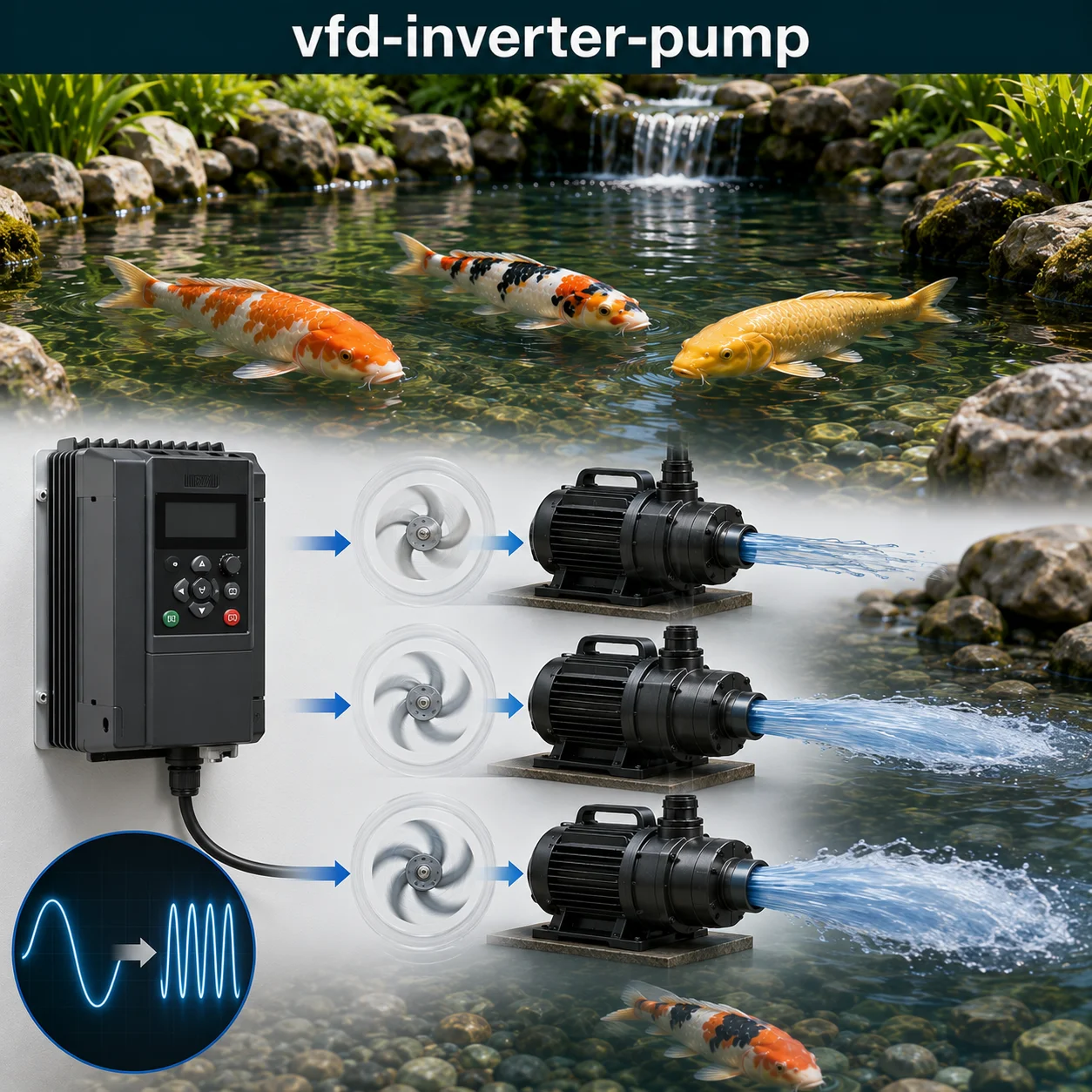
Variable Frequency Drive (VFD) Pump Control and Inverter Energy Optimization
A Variable Frequency Drive (VFD) — also known as an inverter, adjustable speed drive, or variable speed drive — is an electronic power conversion device that controls the speed and torque of an AC electric motor by varying the frequency and voltage of the electrical supply. In a koi pond application, a VFD allows the pump to operate at reduced speeds when full flow is not required, delivering substantial energy savings through the pump affinity laws: flow varies linearly with speed, head varies with the square of speed, and power varies with the cube of speed. A pump running at 80% speed consumes approximately 51% of the power of a pump running at 100% speed — a 49% energy reduction while delivering 80% of the flow.
This page works through the practical engineering behind VFD pump control: the basic principles of variable frequency operation, the affinity laws and their implications for energy savings, control strategies (PID, pressure, flow, temperature), harmonic considerations and power quality, cable selection and installation requirements, integration with pond automation systems, and the practical trade-offs between inverter cost, energy savings, and system reliability. None of the guidance here is a universal rule — pump size, system head curve, operating hours, and utility rates all shift the economics, so every design decision needs to be checked against the specific system rather than a rule of thumb.
VFD Pump Control Challenge
Work through ten advanced questions covering variable speed drive fundamentals, affinity laws, control strategies, harmonics, installation, and optimization. Each answer includes the engineering reasoning behind it.
VFD Pump Control — Quick Facts
Most Asked Questions About VFD Pump Control
A 4,500-gallon pond was circulating with a 3HP pump running continuously at full speed, consuming approximately 2.5 kW (2,500W). The monthly electricity cost was around $270. A VFD was installed with a pressure sensor on the return line, allowing the pump to operate at an average speed of 75%. The system maintained adequate flow for filtration while reducing energy consumption to 1.05 kW — a 58% reduction.
The VFD cost $1,200 including installation, and the monthly electricity savings were $157. The payback was approximately 7.6 months. The pump also ran quieter at reduced speed, and the pond experienced less water disturbance, improving visibility. The VFD’s soft-start feature eliminated the inrush current spike, which had been tripping the circuit breaker during startup.
VFD Operating Principles and Pump Affinity Laws
A Variable Frequency Drive converts fixed-frequency AC power (50/60 Hz) to variable-frequency AC power through a three-stage process:
- Rectification: The input AC is converted to DC using a diode bridge rectifier. This produces a pulsating DC voltage that is smoothed by capacitors.
- DC Bus: The smoothed DC voltage (approximately 1.414 × input voltage, e.g., 325V DC for 230V AC input) is stored on capacitors and supplies power to the inverter stage.
- Inversion: The DC is converted back to AC using IGBTs (Insulated Gate Bipolar Transistors) switching at 2-20 kHz. The output is a PWM (Pulse Width Modulated) waveform that approximates a sine wave at the desired frequency.
The pump affinity laws govern the relationship between speed and performance. The cubic relationship between power and speed is the source of the energy savings: a 10% speed reduction saves 27% power; 20% saves 49%; 30% saves 66%; 40% saves 78%; and 50% saves 87.5%. However, the system head curve and minimum flow requirements limit the practical speed reduction. For a typical pond system with moderate head (5-15 feet), the pump can usually operate at 60-80% speed during low-demand periods while maintaining adequate flow.
Harmonics, Power Quality, and Mitigation Strategies
VFDs generate harmonic currents due to the non-linear nature of the rectifier stage. The harmonics are integer multiples of the fundamental frequency: 5th (300 Hz for 60 Hz), 7th (420 Hz), 11th (660 Hz), 13th (780 Hz), and so on. The total harmonic distortion (THD) of a typical 6-pulse VFD is 30-40% without mitigation. The harmonic currents cause voltage distortion in the supply and can affect other equipment. IEEE 519 recommends limits for voltage and current distortion based on the size of the load relative to the utility. Mitigation strategies include:
- Line reactors: 3-5% impedance reactors reduce THD by 30-50% and provide transient protection
- DC link chokes: Inductors in the DC bus reduce harmonics by smoothing the current waveform
- Passive harmonic filters: LC circuits tuned to specific harmonic frequencies
- Active harmonic filters: IGBT-based active filtering that injects cancelling currents
- Multi-pulse rectifiers: 12-pulse (two rectifiers) or 18-pulse (three rectifiers) designs that cancel lower harmonics
For most pond installations, a 3-5% line reactor on the input is sufficient to meet utility requirements and protect the VFD and other equipment.
During a VFD installation at a large koi facility with three 5HP pumps, the commissioning team noticed that the lighting in the pump house flickered and the control system had intermittent communication errors. Harmonic analysis revealed 38% THD on the supply line caused by the three VFDs without line reactors.
Installing 5% line reactors on each VFD reduced the THD to 12%, and adding a passive harmonic filter brought it below 8%, meeting IEEE 519 requirements. The lighting flicker stopped, and the control system communications became stable. The total cost of the line reactors and filter was $800 — less than 5% of the total system cost.
VFD Installation and Cable Requirements
Proper installation is critical for VFD reliability and performance. Key requirements include:
- VFD Cable: Use shielded VFD cable with symmetrical grounding conductors (3 phase conductors + 3 ground conductors, or 4 conductors with a ground). The shielding must be grounded at both ends or at the VFD only, depending on the manufacturer’s recommendation.
- Maximum Cable Length: Limit the distance between the VFD and motor to: 50-100m for small drives (under 10HP), 100-200m for medium drives, and up to 300m with output filters. Long cable runs cause reflected wave voltage spikes that can damage the motor insulation.
- Environmental Considerations: Mount VFDs in clean, dry, well-ventilated areas. Operating temperature range is typically -10°C to 40°C for standard units, with derating for higher temperatures. Keep VFDs away from direct sunlight, water, and corrosive chemicals.
- Grounding: Use a single-point ground to avoid ground loops. The VFD, motor, and motor cable shield should all be connected to the same grounding point.
For retrofitting existing motors, verify that the motor is “inverter-rated” or has insulation rated for the high-voltage PWM spikes (typically 1,200-1,600V peak). Older motors may require output filters (dv/dt filters or sine wave filters) to protect the insulation.
A 2HP pond pump was retrofitted with a VFD using standard THHN building wire in conduit, run 150 feet from the VFD to the pump. After three months, the pump motor failed with insulation breakdown in the windings. The cause was reflected wave voltage spikes caused by the long cable run with unshielded wire.
The replacement motor was inverter-rated, and the cable was replaced with shielded VFD cable with symmetrical grounding. An output dv/dt filter was installed to reduce the voltage rise time. The new installation has been operating reliably for over two years.
VFD Pump Control — Full Question Library
Review indexed engineering questions below.
Q1:
What does VFD stand for in the context of pump control?
Correct Answer: Option A
VFD stands for Variable Frequency Drive — a device that controls the speed of an AC motor by varying the frequency and voltage of the electrical supply.
Q2:
What are the three main stages of a VFD?
Correct Answer: Option C
A VFD has three main stages: rectifier (AC to DC), DC bus (smoothing and storage), and inverter (DC to variable-frequency AC).
Q3:
What is the typical DC bus voltage for a 230V AC input VFD?
Correct Answer: Option B
The DC bus voltage is approximately 1.414 × the AC input voltage. For 230V AC, the DC bus is approximately 325V DC. For 460V AC, the DC bus is approximately 650V DC.
Q4:
What type of switching device is used in the inverter stage of a modern VFD?
Correct Answer: Option A
Modern VFDs use IGBTs (Insulated Gate Bipolar Transistors) for the inverter stage. They combine high switching speed with high voltage and current ratings.
Q5:
What is the typical switching frequency of a VFD inverter?
Correct Answer: Option C
IGBTs in VFDs typically switch at 2-20 kHz. Higher switching frequencies produce a cleaner output waveform but increase losses and EMI.
Q6:
What is the output waveform of a VFD called?
Correct Answer: Option B
The output of a VFD is a PWM (Pulse Width Modulated) waveform that approximates a sine wave. The PWM signal is filtered by the motor’s inductance to produce a current waveform that is close to a sine wave.
Q7:
What is the relationship between output frequency and motor speed?
Correct Answer: Option A
Motor speed is directly proportional to frequency: Speed = 120 × Frequency ÷ Number of poles. Doubling the frequency doubles the speed.
Q8:
What is the typical output frequency range of a standard VFD?
Correct Answer: Option C
Most VFDs can operate from 0-120 Hz, with some models extending to 400 Hz. For pond pump applications, the practical range is typically 20-60 Hz (since pumps have minimum speed requirements).
Q9:
What is the voltage-to-frequency (V/Hz) ratio maintained by a VFD?
Correct Answer: Option B
For pump applications, the V/Hz ratio is maintained constant (e.g., 460V/60Hz = 7.67 V/Hz) to provide constant torque and avoid motor saturation.
Q10:
What is the purpose of the DC bus capacitors in a VFD?
Correct Answer: Option A
The DC bus capacitors smooth the pulsating DC voltage from the rectifier, providing a stable DC supply for the inverter stage.
Q11:
What is the pump affinity law for flow as a function of speed?
Correct Answer: Option B
Flow is directly proportional to speed: Q₁/Q₂ = N₁/N₂. Reducing speed by 20% reduces flow by 20%.
Q12:
What is the pump affinity law for head as a function of speed?
Correct Answer: Option C
Head is proportional to the square of speed: H₁/H₂ = (N₁/N₂)². Reducing speed by 20% reduces head by 36%.
Q13:
What is the pump affinity law for power as a function of speed?
Correct Answer: Option A
Power is proportional to the cube of speed: P₁/P₂ = (N₁/N₂)³. Reducing speed by 20% reduces power by 49%.
Q14:
What is the energy savings when reducing pump speed from 100% to 80%?
Correct Answer: Option B
Power at 80% speed = (0.8)³ = 0.512 = 51.2% of full power. Savings = 100% – 51.2% = 48.8%.
Q15:
What is the energy savings when reducing pump speed from 100% to 50%?
Correct Answer: Option C
Power at 50% speed = (0.5)³ = 0.125 = 12.5% of full power. Savings = 100% – 12.5% = 87.5%.
Q16:
What is the payback period for a $1,000 VFD on a 2HP pump operating 8,760 hours/year at $0.15/kWh with 30% speed reduction?
Correct Answer: Option A
2HP = 1.5kW. Annual energy cost at full speed = 1.5 × 8,760 × $0.15 = $1,971. At 70% speed: power = (0.7)³ × 1.5 = 0.514kW. Annual cost = 0.514 × 8,760 × $0.15 = $675. Savings = $1,296/year. Payback = $1,000 ÷ $1,296 = 0.77 years (~9 months).
Q17:
What is the energy savings when reducing pump speed from 100% to 90%?
Correct Answer: Option C
Power at 90% speed = (0.9)³ = 0.729 = 72.9% of full power. Savings = 100% – 72.9% = 27.1%.
Q18:
What is the relationship between speed and energy consumption for a pump?
Correct Answer: Option B
Energy consumption for a pump is proportional to the cube of speed, making VFDs highly effective for energy savings.
Q19:
What is the minimum practical speed for a standard centrifugal pump?
Correct Answer: Option A
Most centrifugal pumps should not operate below 30-40% of rated speed due to: (1) insufficient head to move water; (2) motor cooling issues; (3) reduced efficiency. Below 30%, the pump may not produce any flow.
Q20:
What is the typical energy savings range for VFD-controlled pond pumps?
Correct Answer: Option C
Typical energy savings for VFD-controlled pond pumps range from 30-70%, depending on the operating cycle and speed reduction achievable.
Q21:
What is PID control in a VFD system?
Correct Answer: Option A
PID (Proportional-Integral-Derivative) is a control algorithm used in VFDs to maintain a process variable (pressure, flow, temperature) at a setpoint by adjusting the motor speed.
Q22:
What sensor is typically used for PID control of a pond pump?
Correct Answer: Option A
PID control of a pond pump typically uses pressure sensors (for constant pressure), flow meters (for constant flow), or level sensors (for sump level control).
Q23:
What is the purpose of the “setpoint” in a PID control loop?
Correct Answer: Option C
The setpoint is the desired value of the process variable (e.g., desired pressure of 20 psi). The PID controller adjusts the motor speed to maintain the process variable at the setpoint.
Q24:
What is the role of the “proportional” term in PID control?
Correct Answer: Option B
The proportional term responds to the current error (setpoint – process value). A higher proportional gain provides faster response but can cause overshoot or instability.
Q25:
What is the role of the “integral” term in PID control?
Correct Answer: Option A
The integral term accumulates past error over time, eliminating steady-state error. Without integral action, the system would always have a small offset from the setpoint.
Q26:
What is the role of the “derivative” term in PID control?
Correct Answer: Option C
The derivative term predicts future error based on the rate of change of the process variable. It dampens oscillations and improves stability.
Q27:
What is the difference between open-loop and closed-loop control?
Correct Answer: Option B
Open-loop control operates without feedback (e.g., manually setting a speed). Closed-loop control uses feedback from a sensor to maintain a setpoint.
Q28:
What is a typical application for VFD control in a koi pond system?
Correct Answer: Option A
A common VFD application in koi ponds is maintaining constant pressure in a waterfall return, ensuring consistent water flow regardless of filter backwashing or changes in system resistance.
Q29:
What is the purpose of a bypass circuit in a VFD installation?
Correct Answer: Option C
A bypass circuit allows the motor to run at full speed (across the line) if the VFD fails, maintaining critical pond circulation during VFD maintenance or repair.
Q30:
What is the typical control resolution of a VFD?
Correct Answer: Option B
Modern VFDs typically have a control resolution of 0.01 Hz, providing very fine speed control. This is equivalent to approximately 0.3 RPM for a 4-pole motor.
Q31:
What are harmonics in the context of VFDs?
Correct Answer: Option A
Harmonics are distortion in the voltage and current waveforms at integer multiples of the fundamental frequency (e.g., 5th harmonic = 300 Hz for a 60 Hz fundamental).
Q32:
Which harmonics are most significant in a 6-pulse VFD?
Correct Answer: Option C
In a 6-pulse VFD, the 5th, 7th, 11th, and 13th harmonics are the most significant. The magnitudes are approximately 20%, 14%, 9%, and 8% of the fundamental current.
Q33:
What is the typical total harmonic distortion (THD) of a 6-pulse VFD without mitigation?
Correct Answer: Option B
A typical 6-pulse VFD has 30-40% total harmonic distortion (THD) without any mitigation. This can cause problems with other equipment and may violate utility standards.
Q34:
What is a line reactor and what does it do?
Correct Answer: Option A
A line reactor is a three-phase inductor placed on the input of a VFD. It reduces harmonic distortion, limits inrush current, and protects the VFD from voltage transients.
Q35:
What is the typical impedance of a line reactor for a VFD?
Correct Answer: Option C
Line reactors typically have 3-5% impedance. Higher impedance provides more harmonic reduction but can cause voltage drop.
Q36:
What is the purpose of an output filter on a VFD?
Correct Answer: Option B
Output filters (dv/dt filters or sine wave filters) protect the motor from the high-voltage spikes caused by reflected waves in long cable runs, which can damage motor insulation.
Q37:
What is IEEE 519 and why is it relevant to VFDs?
Correct Answer: Option A
IEEE 519 is the standard for harmonic limits in power systems. It sets limits on voltage and current distortion to ensure power quality for all connected equipment.
Q38:
How does a 12-pulse VFD reduce harmonics compared to a 6-pulse VFD?
Correct Answer: Option C
A 12-pulse VFD uses two 6-pulse rectifier bridges phase-shifted by 30°, canceling the 5th and 7th harmonics and reducing THD to 10-12%.
Q39:
What is the effect of high harmonic distortion on other equipment?
Correct Answer: Option B
High harmonic distortion can cause: overheating of transformers and motors; nuisance tripping of circuit breakers; interference with communications and instrumentation; and power factor penalties.
Q40:
What is a passive harmonic filter?
Correct Answer: Option A
A passive harmonic filter is an LC circuit tuned to a specific harmonic frequency. It provides a low-impedance path for that harmonic, reducing its magnitude in the supply.
Q41:
What type of cable is required for VFD installations?
Correct Answer: Option B
VFD installations require shielded cable with symmetrical grounding (3+3+ground or 4+4+ground) to minimize EMI and common-mode currents.
Q42:
What is the maximum recommended cable length for a VFD without an output filter?
Correct Answer: Option A
Maximum cable length without an output filter is typically 50-100m for small drives (under 10HP). Longer runs require output filters to protect the motor from reflected wave voltage spikes.
Q43:
What is the recommended operating temperature range for a VFD?
Correct Answer: Option C
Most VFDs have an operating temperature range of -10°C to 50°C. Operation above 40°C typically requires derating (reducing the output current capacity).
Q44:
How should the shield of VFD cable be grounded?
Correct Answer: Option B
The cable shield should be grounded at the VFD end only (typically). Grounding at both ends can create ground loops. Follow the manufacturer’s specific recommendation.
Q45:
What is the minimum clearance required around a VFD for cooling?
Correct Answer: Option A
VFDs typically require 100-200mm (4-8 inches) of clearance on all sides for adequate airflow. Additional clearance is required for larger drives.
Q46:
What is the recommended wiring practice for VFD control signals?
Correct Answer: Option C
Control signal wiring should use shielded cable in a separate conduit from power wiring to minimize EMI interference. The shield should be grounded at one end.
Q47:
What is the purpose of a ground fault protection device with a VFD?
Correct Answer: Option B
Ground fault protection devices (GFPDs) protect personnel from electrical shock in the event of a ground fault. They are required by code in many installations.
Q48:
What is the typical IP (Ingress Protection) rating for a VFD installed in a pump house?
Correct Answer: Option A
Most VFDs in indoor pump house installations have IP20 rating. For dusty or wet locations, IP54 or higher is required. The manufacturer should specify the appropriate rating.
Q49:
What is the recommended torque for VFD power terminal connections?
Correct Answer: Option C
Terminal torque specifications are critical for safe and reliable connections. Under-torquing can cause overheating; over-torquing can damage the terminal. Use a torque wrench.
Q50:
What is the purpose of a bypass circuit in a VFD installation?
Correct Answer: Option B
A bypass circuit allows the motor to run at full speed (across the line) if the VFD fails, maintaining critical circulation during maintenance or repair.
Q51:
What is the difference between an inverter-rated motor and a standard motor?
Correct Answer: Option B
Inverter-rated motors have: (1) higher insulation voltage ratings to withstand PWM voltage spikes; (2) independent cooling fans for low-speed operation; (3) better bearing protection.
Q52:
What is the minimum insulation voltage rating for a motor used with a VFD?
Correct Answer: Option A
Motors used with VFDs should have insulation rated for 1,200-1,600V peak to withstand the high-voltage spikes from the PWM output. Class F (155°C) or Class H (180°C) insulation is recommended.
Q53:
Why does a motor need additional cooling at low speeds with a VFD?
Correct Answer: Option C
At low speeds, the motor’s shaft-mounted cooling fan provides less airflow, potentially causing the motor to overheat. Inverter-rated motors have independent cooling fans or larger cooling fins.
Q54:
What is the typical minimum frequency for a standard motor with a VFD?
Correct Answer: Option B
Standard motors typically should not be run below 20 Hz (30-40% of rated speed) without additional cooling. Inverter-rated motors can operate down to 0 Hz with adequate cooling.
Q55:
What is the effect of running a standard motor at low speeds with a VFD?
Correct Answer: Option A
Running a standard motor at low speeds for extended periods can cause overheating due to reduced cooling airflow, leading to insulation failure and reduced motor life.
Q56:
What is the role of a dv/dt filter in a VFD installation?
Correct Answer: Option C
A dv/dt filter reduces the rate of voltage change at the motor terminals, protecting the motor insulation from the high-voltage spikes caused by long cable runs.
Q57:
What is the typical voltage rating of a motor used with a 460V VFD?
Correct Answer: Option B
A motor used with a 460V VFD should be rated for 460V. The VFD’s output voltage is proportional to the input voltage and is typically 460V at 60 Hz.
Q58:
What is the purpose of a thermistor or RTD in a VFD-controlled motor?
Correct Answer: Option A
Thermistors or RTDs embedded in the motor windings monitor motor temperature, providing feedback to the VFD to protect against overheating, especially at low speeds.
Q59:
What is the typical efficiency of an inverter-rated motor compared to a standard motor?
Correct Answer: Option C
Inverter-rated motors have similar efficiency to standard motors at rated speed but maintain better efficiency across a wider speed range due to improved design for variable-speed operation.
Q60:
What is the primary bearing failure mechanism in VFD-controlled motors?
Correct Answer: Option B
VFDs can induce shaft voltages in motors, causing electrical discharge through the bearings (EDM). This leads to premature bearing failure. Insulated bearings or shaft grounding rings are recommended.
Q61:
What does PID stand for in control systems?
Correct Answer: Option A
PID stands for Proportional-Integral-Derivative, the three terms of the control algorithm used to maintain a process variable at a setpoint.
Q62:
What is the purpose of the proportional term in PID control?
Correct Answer: Option B
The proportional term responds to the current error (setpoint – process value). A higher proportional gain gives faster response but can cause overshoot.
Q63:
What is the purpose of the integral term in PID control?
Correct Answer: Option C
The integral term eliminates steady-state error by accumulating past error over time. Without integral action, the system would always have a small offset from the setpoint.
Q64:
What is the purpose of the derivative term in PID control?
Correct Answer: Option B
The derivative term predicts future error based on the rate of change of the process variable. It dampens oscillations and improves system stability.
Q65:
What happens if the integral gain is too high in a PID controller?
Correct Answer: Option A
If the integral gain is too high, the controller overreacts to accumulated error, causing the system to oscillate or become unstable (integral windup).
Q66:
What is integral windup in a PID controller?
Correct Answer: Option C
Integral windup occurs when the controller output is saturated (at maximum or minimum limit) and the integral term continues to accumulate error, causing large overshoot when the saturation clears.
Q67:
What is the purpose of anti-windup protection in a PID controller?
Correct Answer: Option B
Anti-windup protection stops the integral term from accumulating error when the controller output is saturated, preventing large overshoot when saturation clears.
Q68:
What is the effect of a slow process response on PID tuning?
Correct Answer: Option A
A slow process response (e.g., a large pond with long piping) requires a higher integral gain to overcome the slow response and achieve the setpoint in a reasonable time.
Q69:
What is the typical setpoint for a pond pump PID controller?
Correct Answer: Option C
For pond pump pressure control, the setpoint is typically 10-30 psi, depending on the system’s elevation and filtration requirements.
Q70:
What is the purpose of the derivative term in a PID controller?
Correct Answer: Option A
The derivative term predicts future error based on the rate of change of the process variable, dampening oscillations and improving system stability.
Q71:
What is the most common cause of VFD faults?
Correct Answer: Option B
Overcurrent and overload faults are the most common VFD faults. They can be caused by mechanical binding, incorrect parameter settings, or motor failure.
Q72:
What is the first step in troubleshooting a VFD fault?
Correct Answer: Option A
The first step is to check the fault code on the VFD display. The fault code identifies the specific fault type and helps guide the troubleshooting process.
Q73:
What is a ground fault in a VFD system?
Correct Answer: Option C
A ground fault is a leakage of current from the motor or cable to ground. It can be caused by damaged insulation, moisture in the motor, or cable damage.
Q74:
What is the typical cause of a “DC bus overvoltage” fault?
Correct Answer: Option B
DC bus overvoltage is typically caused by regenerative energy from the motor (e.g., when the motor is decelerating rapidly). A braking resistor is used to dissipate this energy.
Q75:
What is the typical cause of a “DC bus undervoltage” fault?
Correct Answer: Option A
DC bus undervoltage is typically caused by low input voltage, power loss, or inadequate power supply wiring.
Q76:
What is the typical cause of a “motor overload” fault?
Correct Answer: Option C
Motor overload faults are caused by the motor drawing excessive current for an extended period, typically due to mechanical binding, excessive load, or incorrect parameters.
Q77:
What is the effect of a loose connection on a VFD?
Correct Answer: Option B
Loose connections can cause overheating at the terminal, voltage drop, and intermittent VFD faults due to poor electrical contact.
Q78:
What is the recommended procedure for resetting a VFD after a fault?
Correct Answer: Option A
After a fault, the cause should be investigated before resetting the VFD. Resetting without investigating can cause repeated faults or damage.
Q79:
What is the typical symptom of a failing VFD capacitor?
Correct Answer: Option C
Failing capacitors in the DC bus can cause intermittent faults, reduced DC bus voltage, and eventually complete VFD failure. Capacitors typically last 7-10 years.
Q80:
What is the effect of a VFD operating in a high-temperature environment?
Correct Answer: Option A
VFDs derate (reduce output current capacity) at temperatures above 40°C. Operating above the derating temperature reduces the VFD’s life and can cause premature failure.
Q81:
What communication protocols are commonly used with VFDs?
Correct Answer: Option B
Common VFD communication protocols include Modbus, Profibus, DeviceNet, Ethernet/IP, Profinet, and BACnet. Modbus over RS-485 is the most common for smaller installations.
Q82:
What is the purpose of a building management system (BMS) integration with a VFD?
Correct Answer: Option A
BMS integration allows remote monitoring and control of the VFD, enabling centralized control, alarming, and data logging.
Q83:
What is the purpose of an analog input on a VFD?
Correct Answer: Option C
Analog inputs accept 4-20mA or 0-10V signals from sensors (pressure, flow, level) or controllers, enabling analog speed control of the VFD.
Q84:
What is the purpose of a digital input on a VFD?
Correct Answer: Option B
Digital inputs accept on/off signals for start/stop, fault reset, speed selection, and other discrete control functions.
Q85:
What is the purpose of a relay output on a VFD?
Correct Answer: Option A
Relay outputs provide status signals such as running, fault, speed reached, and alarm conditions. They can be used for indication or interlocking with other equipment.
Q86:
What is the purpose of an analog output on a VFD?
Correct Answer: Option C
Analog outputs provide a 4-20mA or 0-10V signal proportional to a parameter such as motor speed, current, or power. They are used for monitoring or control.
Q87:
What is the typical communication distance for Modbus over RS-485?
Correct Answer: Option B
Modbus over RS-485 can communicate up to 1,200 meters (4,000 feet) at lower baud rates. The distance decreases with higher baud rates.
Q88:
What is the purpose of a PLC (Programmable Logic Controller) in a VFD system?
Correct Answer: Option A
A PLC provides advanced control logic, sequencing, interlocking, and coordination of multiple VFDs and other equipment in a pond system.
Q89:
What is the purpose of a human-machine interface (HMI) with a VFD?
Correct Answer: Option C
An HMI provides a graphical user interface for monitoring the VFD, displaying parameters, adjusting setpoints, and controlling the system.
Q90:
What is the typical power supply requirement for a VFD control circuit?
Correct Answer: Option B
Most VFD control circuits operate on 24V DC, which is the standard for industrial control systems and provides safe, low-voltage control signals.
Q91:
What is sensorless vector control in a VFD?
Correct Answer: Option A
Sensorless vector control uses a mathematical model of the motor to estimate rotor position and speed without an encoder. It provides better torque control than V/Hz control.
Q92:
What is closed-loop vector control in a VFD?
Correct Answer: Option C
Closed-loop vector control uses an encoder or resolver for precise speed and position feedback, providing the highest torque control and speed regulation accuracy.
Q93:
What is the purpose of an encoder in a VFD system?
Correct Answer: Option B
An encoder provides accurate speed and position feedback to the VFD, enabling closed-loop vector control for precise speed regulation.
Q94:
What is a braking resistor and when is it needed?
Correct Answer: Option A
A braking resistor dissipates regenerative energy from the motor during deceleration, preventing DC bus overvoltage faults. It is needed for applications with frequent or rapid deceleration.
Q95:
What is the typical duty cycle for a braking resistor?
Correct Answer: Option C
Braking resistors are typically rated for 5-10% duty cycle (intermittent operation). Continuous braking would require a much larger resistor and is not typical for pond pump applications.
Q96:
What is the purpose of a sine wave filter on a VFD output?
Correct Answer: Option B
A sine wave filter converts the PWM output to a near-sinusoidal waveform, reducing motor heating and acoustic noise. It is used for long cable runs or sensitive motors.
Q97:
What is the typical efficiency of a modern VFD?
Correct Answer: Option A
Modern VFDs have efficiencies of 95-98% at rated load. The efficiency decreases at partial load but still remains high.
Q98:
What is the effect of a VFD on motor power factor?
Correct Answer: Option C
VFDs typically improve the motor’s power factor to near unity by controlling the voltage and current relationship, reducing reactive power demand.
Q99:
What is a common cause of EMI (Electromagnetic Interference) from a VFD?
Correct Answer: Option B
The high-frequency PWM switching of the IGBTs generates EMI, which can affect sensitive equipment. Proper shielding and grounding are required to meet EMC standards.
Q100:
What is the typical lifespan of a VFD?
Correct Answer: Option A
The typical lifespan of a VFD is 7-10 years. The DC bus capacitors are the most common failure component, with a typical lifespan of 7-10 years depending on operating temperature and load.