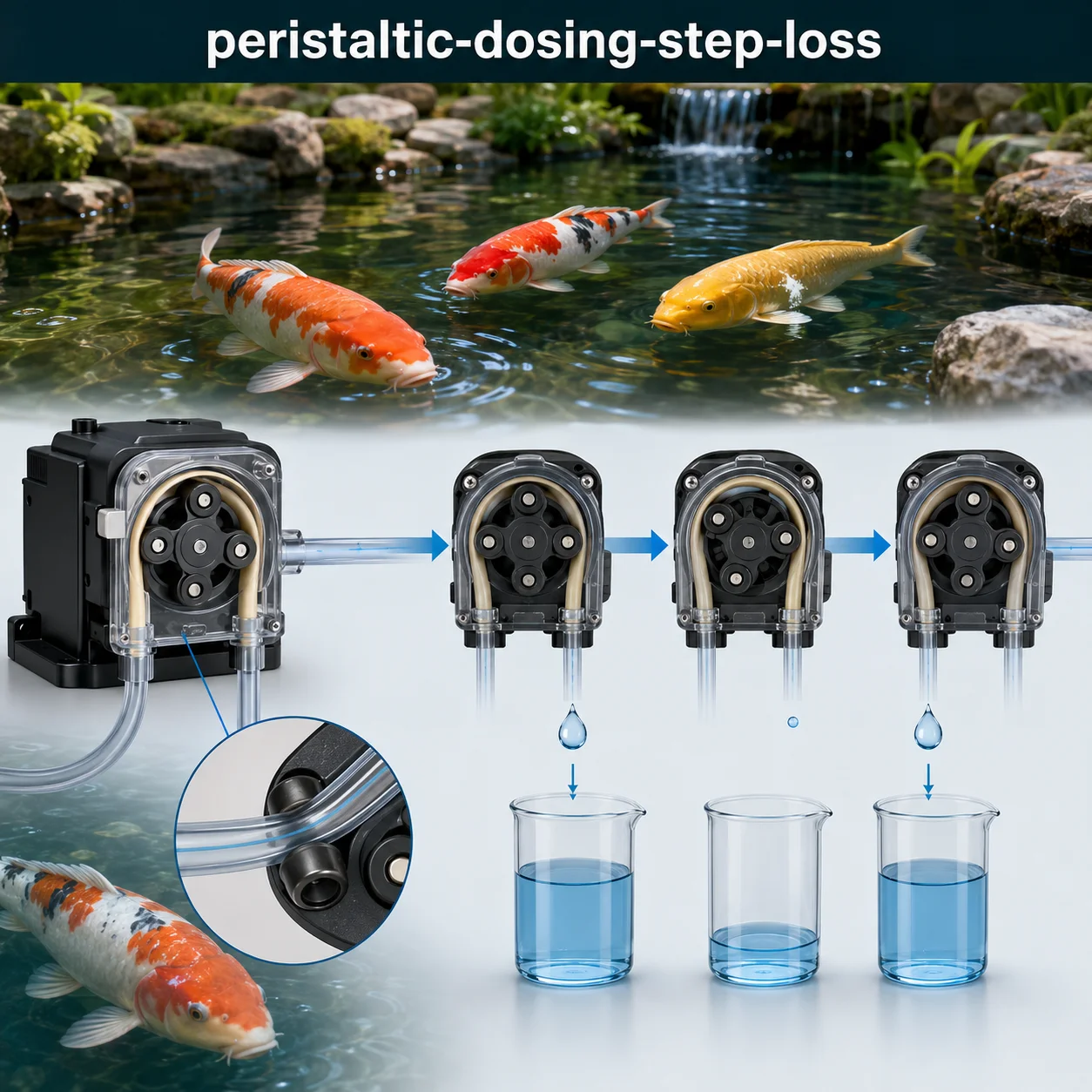
Stepper Motor Peristaltic Dosing Step-Loss Metrics and PWM Titration Errors
Stepper motor-driven peristaltic pumps are the workhorses of precision dosing in koi pond automation — delivering measured volumes of pH adjusters, flocculants, dechlorinators, and other treatment chemicals with theoretical accuracy that depends entirely on the motor’s ability to execute every commanded step. A stepper motor operates by energizing its windings in sequence, causing the rotor to move through discrete angular steps — typically 1.8° per step (200 steps/revolution) in full-step mode, or fractions of a step (microsteps) when driven by microstepping drivers. When every step is executed correctly, the relationship between commanded steps and delivered volume is linear and predictable. When steps are lost — due to mechanical binding, insufficient torque, electrical noise, or excessive acceleration — the pump under-doses, and the accumulated error can undermine the entire treatment protocol.
This page works through the practical engineering behind stepper motor peristaltic dosing: the operating principles of stepper motors and peristaltic pumps, step-loss mechanisms and detection, PWM titration errors (including nonlinearity and resolution limits), calibration strategies, tube wear compensation, and the practical trade-offs between speed, torque, and dosing accuracy. None of the guidance here is a universal rule — tube type, fluid viscosity, back pressure, motor driver settings, and environmental factors all shift the performance, so every design decision needs to be checked against the specific system rather than a rule of thumb.
Stepper Motor Peristaltic Dosing Challenge
Work through ten advanced questions covering stepper motor fundamentals, step-loss metrics, PWM titration errors, calibration, and troubleshooting. Each answer includes the engineering reasoning behind it.
Stepper Motor Peristaltic Dosing — Quick Facts
Most Asked Questions About Stepper Motor Peristaltic Dosing
A pH control system using a stepper motor peristaltic pump to deliver acid was consistently under-dosing by 8-12%, causing the pond pH to drift upward despite the controller calling for acid. The problem was intermittent — sometimes the dosing was accurate, sometimes it was significantly low.
Investigation revealed step loss caused by a combination of factors: the pump tubing had aged and lost elasticity (reducing the flow rate), the stepper motor driver was configured for 1/32 microstepping (reducing holding torque), and the PWM frequency was set too low, causing audible vibration at low speeds. The solution was to replace the tubing, reconfigure the driver to 1/16 microstepping (improving torque), and increase the PWM frequency to eliminate vibration. The dosing accuracy improved to within ±2%.
Stepper Motor Fundamentals and Microstepping
Stepper motors are brushless DC motors that divide a full rotation into a number of discrete steps. The key specifications for dosing applications are:
- Step Angle: The angular displacement per step. Standard motors have 1.8° (200 steps/rev) or 0.9° (400 steps/rev). Higher resolution motors provide finer control but require more complex drivers.
- Holding Torque: The torque the motor can generate when stationary with current applied. Higher holding torque reduces the risk of step loss when the pump is under load.
- Detent Torque: The torque required to move the motor when de-energized (due to permanent magnets in the rotor). This can affect the ability to hold position when the motor is unpowered.
- Microstepping: Divides each full step into smaller increments. 1/16 microstepping (3,200 steps/rev) is common for dosing pumps. The microstepping resolution must be balanced against torque reduction (approximately 30% torque loss at 1/16 step).
The relationship between steps and rotation is: Rotation (rad) = Steps × Step_Angle × π ÷ 180. For example, 100 steps on a 1.8° motor = 100 × 1.8° = 180° = 0.5 revolution.
PWM Titration Control and Resolution
PWM (Pulse Width Modulation) is used to control the speed of the stepper motor (by controlling the step pulse frequency) and the motor current (by controlling the winding current). The key considerations for dosing accuracy are:
- PWM Resolution: An 8-bit PWM provides 256 levels (0-255), giving approximately 0.4% speed resolution. A 16-bit PWM provides 65,536 levels, giving 0.0015% resolution. For dosing applications, 12-16 bit resolution is recommended for precise speed control.
- PWM Frequency: The frequency should be above the audible range (>20 kHz) to avoid noise, but not so high that it causes excessive heating in the motor windings. Typical frequencies are 20-50 kHz for stepper motor drivers.
- Nonlinearity: The relationship between PWM duty cycle and motor speed is not perfectly linear. The motor may not start moving until a minimum duty cycle is reached (dead zone), and the speed may increase more rapidly at higher duty cycles. This nonlinearity should be characterized during calibration.
- Voltage Regulation: Variations in the supply voltage (typically ±10% from nominal) cause changes in motor current and torque, which can affect step accuracy and increase the risk of step loss.
Proper PWM setup includes: (1) Selecting a suitable PWM resolution (≥12-bit); (2) Setting the PWM frequency above 20 kHz; (3) Characterizing the PWM-to-speed curve for calibration; (4) Using a regulated power supply to maintain consistent voltage.
A dosing system for a 5,000-gallon pond was delivering inconsistent amounts of dechlorinator, sometimes over-dosing and sometimes under-dosing. The system used an 8-bit PWM (0-255) for speed control, and the operator was using settings around 25% duty cycle (PWM value 64).
Analysis revealed that at low PWM values, the motor speed was highly nonlinear — a change from PWM 60 to 65 caused a 15% change in speed, while a change from 120 to 125 caused only a 2% change. The system was operating in the most nonlinear region of the control curve. The solution was to replace the 8-bit PWM with a 16-bit system and re-characterize the speed curve, allowing the system to operate in a more linear region with finer control.
Step-Loss Detection and Compensation
Step-loss detection and compensation are essential for reliable dosing accuracy. The primary methods include:
- Stall Detection: Monitors the motor current or back-EMF to detect when the motor is not turning when commanded. A sudden drop in current (indicating a stall) or a lack of back-EMF (indicating no rotation) can trigger a fault or compensation action.
- Encoder Feedback: A rotary encoder on the motor shaft provides absolute position feedback, allowing the controller to detect and compensate for step loss. Closed-loop stepper systems use encoders to ensure positional accuracy.
- Current Monitoring: Tracking the motor current over time can detect step loss — when a step is lost, the current may spike or drop, indicating a fault condition.
- Positional Error Tracking: The controller maintains a count of commanded steps and compares it to the actual position (from encoder feedback). If the error exceeds a threshold, the system can re-synchronize or generate an alarm.
For dosing applications, closed-loop stepper systems with encoder feedback provide the highest accuracy and reliability, but they are more expensive than open-loop systems. Open-loop systems can still achieve good accuracy with proper design, calibration, and regular maintenance.
A 2,500-gallon pond was using a peristaltic pump to deliver pH buffer solution. The pump would occasionally lose steps during the startup phase, resulting in a 3-5% under-dose that was not detected until the pH had drifted significantly.
The solution was to install a stall detection circuit that monitored the motor current. When a stall was detected, the system would: (1) Stop the motor; (2) Re-home the pump (rotate to a known reference position); (3) Resume the dosing cycle from the beginning. This ensured that no dosing was missed and that the correct volume was delivered. The system has been operating reliably for over two years.
Stepper Motor Peristaltic Dosing — Full Question Library
Review indexed engineering questions below.
Q1:
What is the step angle of a standard stepper motor?
Correct Answer: Option A
The standard stepper motor has a step angle of 1.8°, which corresponds to 200 steps per revolution (360° ÷ 1.8° = 200).
Q2:
How many steps per revolution does a 1.8° stepper motor have?
Correct Answer: Option C
A 1.8° stepper motor has 200 steps per revolution (360° ÷ 1.8° = 200).
Q3:
What is the step angle of a high-resolution stepper motor?
Correct Answer: Option B
High-resolution stepper motors have a step angle of 0.9°, providing 400 steps per revolution for finer positioning control.
Q4:
What type of motor is a stepper motor?
Correct Answer: Option A
Stepper motors are brushless DC motors that use permanent magnets in the rotor and electromagnets in the stator to create discrete angular steps.
Q5:
What is holding torque in a stepper motor?
Correct Answer: Option C
Holding torque is the maximum torque that the motor can generate when stationary (with current applied to the windings) to hold the rotor in position.
Q6:
What is detent torque in a stepper motor?
Correct Answer: Option B
Detent torque is the residual torque required to rotate the motor when the windings are unpowered, caused by the permanent magnets in the rotor interacting with the stator.
Q7:
What is the typical motor winding configuration for a stepper motor?
Correct Answer: Option A
Stepper motors are available in bipolar (two windings, each with a center tap) or unipolar (two windings, no center tap) configurations. Bipolar motors provide more torque but require more complex drivers.
Q8:
What is the effect of microstepping on holding torque?
Correct Answer: Option C
Microstepping reduces holding torque. At 1/16 microstepping, the holding torque is approximately 70% of the full-step holding torque.
Q9:
What is the typical current rating for a NEMA 17 stepper motor used in dosing applications?
Correct Answer: Option B
Typical NEMA 17 stepper motors used in dosing applications have current ratings of 1.0-2.0 A per phase, providing adequate torque for peristaltic pump operation.
Q10:
What is the relationship between step frequency and motor speed?
Correct Answer: Option A
Motor speed (RPM) = (Step frequency in Hz × 60) ÷ (Steps per revolution). For a 1.8° motor (200 steps/rev), 1,000 Hz = 300 RPM.
Q11:
How does a peristaltic pump move fluid?
Correct Answer: Option B
A peristaltic pump moves fluid by compressing a flexible tube with rotating rollers, creating a positive displacement that propels the fluid through the tube.
Q12:
What is the typical number of rollers in a peristaltic pump head?
Correct Answer: Option A
Peristaltic pump heads typically have 2-6 rollers. More rollers provide smoother flow (less pulsation) but reduce the flow rate per revolution.
Q13:
What is the relationship between tube ID and flow rate in a peristaltic pump?
Correct Answer: Option C
Flow rate is proportional to the cross-sectional area of the tube (π × r²), which is proportional to the square of the inner diameter (ID).
Q14:
What is the effect of back pressure on a peristaltic pump?
Correct Answer: Option B
Back pressure reduces the flow rate of a peristaltic pump by causing the tube to deform under pressure and by allowing some fluid to slip past the compression point.
Q15:
What is tube compression in a peristaltic pump?
Correct Answer: Option A
Tube compression is the amount the flexible tube is squeezed by the rollers against the pump housing. Proper compression is essential for sealing and preventing backflow.
Q16:
What is the typical maximum back pressure for a standard peristaltic pump?
Correct Answer: Option C
Standard peristaltic pumps typically handle 5-15 psi back pressure. High-pressure designs can handle up to 100 psi with reinforced tubing.
Q17:
What is the effect of tube material on pump performance?
Correct Answer: Option B
Tube material affects flexibility (affects flow rate and pressure capability), chemical resistance (affects compatibility with fluids), and wear life (affects maintenance frequency).
Q18:
What is pulsation in a peristaltic pump and how is it minimized?
Correct Answer: Option A
Pulsation is the flow variation caused by the compression and release of the tube by the rollers. It is minimized by using more rollers (3-6) or by adding a pulsation damper to the outlet line.
Q19:
What is the typical tube life for silicone tubing in a peristaltic pump?
Correct Answer: Option C
Silicone tubing typically lasts 500-2,000 hours in peristaltic pump operation, depending on the fluid, speed, and compression force.
Q20:
What is the formula for calculating flow rate in a peristaltic pump?
Correct Answer: Option A
The flow rate is calculated from the tube cross-sectional area, the rotational speed, the number of rollers, and a compression factor that accounts for the tube deformation.
Q21:
What is step loss in a stepper motor?
Correct Answer: Option B
Step loss occurs when the motor fails to move the commanded number of steps, resulting in positional error and inaccurate dosing.
Q22:
What is the most common cause of step loss in a dosing pump?
Correct Answer: Option A
The most common cause of step loss is insufficient torque to overcome the load (mechanical resistance, back pressure, or binding).
Q23:
How can step loss be detected in a stepper motor?
Correct Answer: Option C
Step loss can be detected using stall detection circuits, encoder feedback, current monitoring, or back-EMF analysis.
Q24:
What is the effect of resonance on step loss?
Correct Answer: Option B
Resonance occurs when the motor operates at a speed that excites its natural frequency, causing vibration that can cause step skipping.
Q25:
What is positional error in a stepper motor dosing system?
Correct Answer: Option A
Positional error is the difference between the number of steps commanded and the number of steps actually executed by the motor. Accumulated positional error causes dosing inaccuracies.
Q26:
What is a stall condition in a stepper motor?
Correct Answer: Option C
A stall condition occurs when the motor is energized but unable to turn due to excessive load. This causes rapid step loss and can damage the motor or driver.
Q27:
What is the effect of acceleration on step loss?
Correct Answer: Option B
Excessive acceleration causes the motor to try to accelerate faster than it can follow, resulting in step loss. Ramp-up should be gradual to avoid this.
Q28:
What is the typical step loss recovery method in a dosing system?
Correct Answer: Option A
When step loss is detected, the standard recovery method is to stop the motor, re-home the pump (move to a known reference position), and resume the dosing cycle from the beginning.
Q29:
What is the relationship between microstepping and step loss risk?
Correct Answer: Option C
Higher microstepping provides smoother motion and reduces resonance, which can decrease step loss risk. However, it also reduces holding torque, which can increase step loss risk under load.
Q30:
How does encoder feedback prevent step loss?
Correct Answer: Option B
An encoder provides real-time position feedback, allowing the controller to detect when steps are lost and compensate by adding additional steps to correct the position.
Q31:
What is PWM and how is it used in stepper motor dosing?
Correct Answer: Option B
PWM is used to control the speed of stepper motors by generating the step pulses at a variable frequency, allowing precise speed control for dosing.
Q32:
What is the typical PWM resolution for dosing applications?
Correct Answer: Option A
Dosing applications typically use 12-16 bit PWM resolution (4,096-65,536 levels) for precise speed control. 8-bit (256 levels) provides only 0.4% resolution, which may not be sufficient.
Q33:
What is the effect of PWM frequency on motor operation?
Correct Answer: Option C
PWM frequency affects the motor’s acoustic noise and vibration. Frequencies above 20 kHz are typically used to avoid audible noise. Higher frequencies may cause increased heating in the motor.
Q34:
What is PWM nonlinearity in motor control?
Correct Answer: Option B
PWM nonlinearity occurs when the motor speed does not increase linearly with the PWM duty cycle, especially at low duty cycles (dead zone) and high duty cycles (saturation).
Q35:
What is the dead zone in PWM motor control?
Correct Answer: Option A
The dead zone is the range of low PWM duty cycles where the motor does not produce enough torque to start moving. This is typically 5-15% of the full PWM range.
Q36:
What is the effect of voltage variation on PWM-controlled stepper motors?
Correct Answer: Option C
Voltage variation (typically ±10% from nominal) changes the motor current and torque, which can affect step accuracy and increase the risk of step loss.
Q37:
What is the typical PWM frequency used in stepper motor drivers?
Correct Answer: Option B
Most stepper motor drivers use PWM frequencies of 20-50 kHz to balance noise suppression, heating, and efficiency.
Q38:
What is the relationship between PWM resolution and dosing accuracy?
Correct Answer: Option A
Higher PWM resolution provides more precise speed control, allowing finer adjustments to the dosing rate and improving overall dosing accuracy.
Q39:
What is the effect of a dirty or noisy PWM signal on motor operation?
Correct Answer: Option C
Noise or jitter in the PWM signal can cause the motor to behave erratically, leading to step loss and inconsistent dosing.
Q40:
What is the recommended method for calibrating PWM speed control?
Correct Answer: Option A
The recommended method is to measure the actual motor speed at multiple PWM values (e.g., 10%, 20%, 30%, …, 100%) and create a calibration curve to correct for nonlinearity.
Q41:
What is a stepper motor driver and what does it do?
Correct Answer: Option B
A stepper motor driver receives step and direction signals from the controller and converts them into the appropriate current sequences in the motor windings to move the motor.
Q42:
What is the typical microstepping setting for a dosing pump driver?
Correct Answer: Option A
Dosing pump drivers typically use 1/16 to 1/32 microstepping, balancing smooth motion and torque for accurate dosing.
Q43:
What is the purpose of the current limit setting on a stepper motor driver?
Correct Answer: Option C
The current limit setting prevents the driver from supplying more current than the motor can safely handle, preventing overheating and damage to the motor and driver.
Q44:
What is the effect of increasing the driver current on motor torque?
Correct Answer: Option B
Increasing the driver current increases the motor’s torque, up to the motor’s rated current limit. Exceeding the rated current can cause overheating.
Q45:
What is the purpose of the decay mode setting on a stepper motor driver?
Correct Answer: Option A
The decay mode (fast decay, slow decay, mixed decay) controls how the current decreases in the motor windings, affecting the torque characteristics and acoustic noise.
Q46:
What is the typical supply voltage for a NEMA 17 stepper motor driver?
Correct Answer: Option C
Stepper motor drivers for NEMA 17 motors typically operate on 12-48V DC. Higher voltages allow higher speeds but require careful current limiting.
Q47:
What is the effect of the step signal frequency on motor speed?
Correct Answer: Option B
The motor speed is directly proportional to the step frequency. Higher step frequencies cause the motor to rotate faster (up to the motor’s maximum speed limit).
Q48:
What is the purpose of a ramp-up (acceleration) profile in motor control?
Correct Answer: Option A
A ramp-up profile gradually increases the motor speed from zero to the target speed, preventing step loss caused by excessive acceleration.
Q49:
What is the purpose of a ramp-down (deceleration) profile in motor control?
Correct Answer: Option C
A ramp-down profile gradually decreases the motor speed, preventing mechanical shock and reducing the risk of step loss during deceleration.
Q50:
What is the recommended practice for stepper motor driver configuration?
Correct Answer: Option B
The driver should be configured for the specific application, including setting the correct current limit for the motor, selecting appropriate microstepping resolution, and choosing the optimal decay mode.
Q51:
How often should a peristaltic dosing pump be calibrated?
Correct Answer: Option B
Peristaltic pumps should be calibrated every 100-500 hours of operation to account for tube wear, which progressively reduces the flow rate.
Q52:
What is the calibration procedure for a peristaltic dosing pump?
Correct Answer: Option A
The calibration procedure involves measuring the actual volume delivered over a known number of steps (or revolutions) and calculating a correction factor (Actual ÷ Commanded) to apply to all future dosing commands.
Q53:
What is the effect of tube wear on calibration?
Correct Answer: Option C
As the tube wears, its internal volume decreases and elasticity is lost, reducing the flow rate. This requires recalibration to maintain dosing accuracy.
Q54:
What is the typical flow rate reduction due to tube wear over 500 hours?
Correct Answer: Option B
Over 500 hours of operation, tube wear typically causes a 5-15% reduction in flow rate, depending on the fluid, speed, and compression force.
Q55:
What is the recommended calibration interval for a new tube?
Correct Answer: Option A
New tubes should be calibrated immediately after installation (after the initial break-in period of 10-30 minutes) to establish the baseline flow rate, and then regularly thereafter.
Q56:
How does fluid viscosity affect dosing calibration?
Correct Answer: Option C
Higher viscosity fluids create more resistance in the tube, reducing the flow rate for a given speed. The pump should be calibrated with the actual dosing fluid.
Q57:
What is the effect of temperature on peristaltic pump calibration?
Correct Answer: Option B
Temperature affects both the fluid viscosity (higher temperature = lower viscosity = higher flow rate) and the tube flexibility (higher temperature = softer tube = different flow characteristics).
Q58:
What is the purpose of a correction factor in dosing calibration?
Correct Answer: Option A
A correction factor (Actual Volume ÷ Commanded Volume) is applied to all dosing commands to compensate for the difference between theoretical and actual delivery.
Q59:
What is the recommended calibration method for high-accuracy dosing?
Correct Answer: Option C
For high-accuracy dosing, calibrate at multiple speed points (e.g., 10%, 50%, 100% of maximum speed) to create a speed-dependent correction curve.
Q60:
What is the effect of tube compression on flow rate?
Correct Answer: Option A
Higher compression reduces the tube’s internal cross-sectional area and can reduce the flow rate, but it is necessary to prevent backflow and ensure consistent dosing.
Q61:
What is the most commonly used tube material for peristaltic pumps?
Correct Answer: Option B
Silicone is the most commonly used tube material for peristaltic pumps due to its excellent flexibility, chemical resistance, and long service life.
Q62:
What is the typical tube replacement interval for a peristaltic pump?
Correct Answer: Option A
The typical tube replacement interval is 500-2,000 hours, depending on the tube material, fluid, speed, and compression force.
Q63:
What is the effect of chemical compatibility on tube selection?
Correct Answer: Option C
The tube material must be chemically compatible with the dosing fluid to prevent swelling, hardening, cracking, or dissolution of the tube material.
Q64:
What is the effect of tube hardness on pump performance?
Correct Answer: Option B
Softer tubes (lower durometer) provide better sealing and lower leakage but may wear faster. Harder tubes (higher durometer) provide longer life but may require more compression force.
Q65:
What is the recommended tube wall thickness for peristaltic pumps?
Correct Answer: Option A
Typical tube wall thickness for peristaltic pumps is 1.6-2.4 mm, providing adequate flexibility and durability for most applications.
Q66:
What are the signs that a peristaltic pump tube needs replacement?
Correct Answer: Option C
Signs that a tube needs replacement include reduced flow rate (despite the same speed), visible cracking or wear, loss of elasticity, and changes in the tube’s color or texture.
Q67:
What is the effect of over-compression of the tube?
Correct Answer: Option B
Over-compression of the tube can cause premature wear, cracking, and failure. The compression should be just enough to seal the tube and prevent backflow.
Q68:
What is the recommended tube storage condition?
Correct Answer: Option A
Tubes should be stored in cool, dry conditions away from direct sunlight, ozone, and chemicals to prevent degradation and extend shelf life.
Q69:
What is the effect of tube length on pump performance?
Correct Answer: Option C
Longer tubes increase the pressure drop in the system, which can reduce the flow rate and increase the load on the motor, increasing the risk of step loss.
Q70:
What is the effect of tube ID variation on dosing accuracy?
Correct Answer: Option A
Flow rate is proportional to the square of the tube ID. A 10% variation in tube ID causes approximately a 21% variation in flow rate, significantly affecting dosing accuracy.
Q71:
What is the most common symptom of step loss in a dosing pump?
Correct Answer: Option B
The most common symptom of step loss is inconsistent or under-dosing, as the motor moves fewer steps than commanded and delivers less fluid.
Q72:
What should be checked first when troubleshooting step loss?
Correct Answer: Option A
Mechanical binding is the most common cause of step loss and should be checked first. Inspect the tube for kinks, the rollers for smooth rotation, and the drive train for obstructions.
Q73:
What is the effect of a worn tube on step loss?
Correct Answer: Option C
A worn tube can cause increased friction (if it has become sticky or degraded) or binding (if it has deformed), both of which can cause step loss.
Q74:
What is the effect of low motor current on step loss?
Correct Answer: Option B
Low motor current reduces the torque available to overcome the load, increasing the risk of step loss. The current should be set to the motor’s rated value.
Q75:
What is the effect of excessive acceleration on step loss?
Correct Answer: Option A
Excessive acceleration causes the motor to try to accelerate faster than it can follow, resulting in step loss. A gradual ramp-up should be used.
Q76:
What is the effect of electrical noise on stepper motor operation?
Correct Answer: Option C
Electrical noise on the step signal lines can cause the motor to receive false step pulses, leading to erratic operation and step loss. Shielded cables and proper grounding are essential.
Q77:
What is the effect of resonance on stepper motor operation?
Correct Answer: Option B
Resonance occurs at certain speeds and can cause vibration that leads to step loss. Microstepping and mechanical damping can help reduce resonance.
Q78:
What is the recommended troubleshooting process for a dosing pump with step loss?
Correct Answer: Option A
The recommended troubleshooting process is: (1) Check mechanical components (tube, rollers, binding); (2) Check electrical components (current, voltage, connections); (3) Check software (microstepping, PWM settings, acceleration).
Q79:
What is the effect of a loose coupling between the motor and the pump head?
Correct Answer: Option C
A loose coupling allows the motor to turn without fully driving the pump head, causing the delivered volume to be less than commanded and resulting in step loss.
Q80:
What is the effect of over-tightening the tube in the pump head?
Correct Answer: Option B
Over-tightening the tube in the pump head increases the friction between the tube and the rollers, increasing the motor load and potentially causing step loss.
Q81:
How is a stepper motor controlled in a pond automation system?
Correct Answer: Option B
Stepper motors are controlled by step and direction signals from a controller (e.g., Arduino, PLC, dedicated dosing controller), which determine the speed and direction of rotation.
Q82:
What communication protocol is commonly used for dosing pump control?
Correct Answer: Option A
Dosing pumps are commonly controlled via Modbus (RS-485 or TCP/IP), 4-20mA analog signals, or discrete step/direction signals from a controller.
Q83:
What is the purpose of a safety interlock in a dosing system?
Correct Answer: Option C
A safety interlock prevents the pump from operating if a fault condition exists (e.g., low fluid level, high back pressure, step loss), preventing over-dosing.
Q84:
What is the purpose of a flow sensor in a dosing system?
Correct Answer: Option B
A flow sensor provides feedback on the actual flow rate, allowing closed-loop control that can compensate for tube wear, back pressure, and other variations.
Q85:
What is the purpose of a pressure sensor in a dosing system?
Correct Answer: Option A
A pressure sensor monitors the back pressure on the pump outlet, detecting blockages or excessive resistance that could cause step loss.
Q86:
What is the purpose of a level sensor in a dosing system?
Correct Answer: Option C
A level sensor prevents the pump from running dry by detecting when the fluid level is low, which would cause the pump to draw air and lose prime.
Q87:
What is the recommended power supply for a stepper motor dosing system?
Correct Answer: Option B
A regulated DC power supply with adequate current capacity (at least 2× the motor’s rated current) is recommended for reliable stepper motor operation.
Q88:
What is the purpose of a bypass valve in a dosing system?
Correct Answer: Option A
A bypass valve relieves pressure in the dosing line, preventing over-pressurization that could damage the pump or tubing and preventing step loss from excessive back pressure.
Q89:
What is the purpose of a check valve in a dosing system?
Correct Answer: Option C
A check valve prevents backflow when the pump is off, maintaining the prime in the tube and preventing contamination or back-siphoning of the dosing fluid.
Q90:
What is the recommended tubing for the suction side of a peristaltic pump?
Correct Answer: Option A
The suction side tubing should be the same as the pump tubing (or reinforced tubing) to prevent collapse under vacuum. Rigid piping can also be used but may require additional fittings.
Q91:
What is a closed-loop stepper motor system?
Correct Answer: Option A
A closed-loop stepper motor system uses an encoder or other feedback device to continuously monitor the motor position and correct for step loss, providing the accuracy of a servo motor with the simplicity of a stepper motor.
Q92:
What is the advantage of a closed-loop stepper motor over an open-loop system?
Correct Answer: Option C
The primary advantage of a closed-loop stepper motor system is that it eliminates step loss by continuously monitoring and correcting the position, ensuring accurate dosing.
Q93:
What is the typical response time of a closed-loop stepper system?
Correct Answer: Option B
Closed-loop stepper systems typically respond to positional errors within 10-50 ms, allowing real-time correction of step loss.
Q94:
What is the effect of encoder resolution on dosing accuracy?
Correct Answer: Option A
A higher resolution encoder provides more precise position feedback, allowing finer correction of positional errors and improving dosing accuracy.
Q95:
What is the typical encoder resolution used in dosing applications?
Correct Answer: Option C
Typical encoder resolution for dosing applications is 400-1000 pulses per revolution (PPR), providing adequate position feedback for accurate dosing.
Q96:
What is the effect of backlash in a peristaltic pump drive train?
Correct Answer: Option B
Backlash in the drive train (gears, couplings) causes a delay between motor rotation and pump rotation, which can cause dosing errors when the motor reverses direction.
Q97:
What is the typical backlash in a gear-coupled stepper motor system?
Correct Answer: Option A
Typical backlash in a gear-coupled system is 0.5-2 degrees, which corresponds to 0.5-2 steps on a 1.8° motor. This should be accounted for in dosing calculations.
Q98:
What is the effect of temperature on stepper motor torque?
Correct Answer: Option C
As the motor temperature increases, the strength of the permanent magnets decreases, reducing the motor’s torque capability and increasing the risk of step loss.
Q99:
What is the typical motor temperature rise in a stepper motor?
Correct Answer: Option A
Typical temperature rise in a stepper motor operating at rated current is 30-50°C above ambient. The motor should be derated if operated at higher temperatures.
Q100:
What is the typical lifespan of a stepper motor in continuous dosing operation?
Correct Answer: Option A
Stepper motors typically last 5,000-15,000 hours in continuous operation, depending on the load, temperature, and operating conditions.